1Safety
Read this section before powering the instrument. The Model 970-X supplies detector bias voltage up to 2000 V positive. Treat every detector input, cable, and connector as live whenever the unit is on. Switch the unit off and confirm the high voltage has discharged before connecting or disconnecting a detector.
General precautions
- Connect detectors only with the unit powered off. The active high voltage supply is enabled and set in software, so verify the bias is at 0 V before you handle cables.
- Use the correct connector for each input. Input 1 carries signal and high voltage on one series "C" connector. Input 2 separates them across an SHV connector for high voltage and a BNC connector for signal.
- Do not exceed the rated bias for the connected detector. Set bias to the detector manufacturer's recommended operating voltage.
- Keep the instrument dry. It is laboratory and field electronics, not a sealed submersible enclosure.
- Service and internal access should be performed by qualified personnel only.
2What's in the Box
The Model 970-X ships with the items needed to install the software and connect to a host computer. The detector is selected and supplied separately to match the application.
- Model 970-X portable MCA
- SNAP-MCA software (Simple Nuclear Analysis Program), single-user license
- Carrying case
- USB-to-serial adapter
Inspect the carrying case and instrument on arrival. Shipping weight is approximately 9 lbs in an 18 x 18 x 13 inch carton. Report any transit damage before powering the unit.
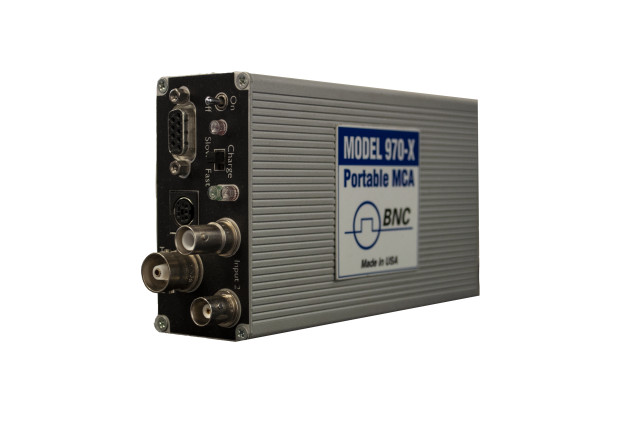
3Hardware Overview
The Model 970-X is a compact, modular pMCA built for real-time processing of gamma, neutron, and x-ray data. It runs as a benchtop laboratory instrument, a process monitor, or an integrated component inside an existing control system.
Detector inputs
The unit provides two detector inputs, with the active input selected in software:
- Input 1: standard series "C" connector. Signal is joined with the high voltage supply on a single connector.
- Input 2: separate connections, an SHV connector for high voltage and a BNC connector for signal.
The inputs accept negative, positive, or pre-shaped (positive) signals, which supports a broad range of detector front ends.
High voltage supply
The internal bias supply delivers 0 to 2000 V positive with an output capacity up to 0.5 mA. Negative high voltage is available on request. Set the bias value in software to match the connected detector.
Amplifier and shaping
Shaping time is adjustable from 0.25 to 10 microseconds. Gain ranges from x1 to x25 through coarse and fine gain controls, which lets you place the spectrum of interest across the available channels.
External connector and USB
An external connector supplies +5 V, +12 V, and -12 V for external preamplifiers and provides two logic signals for external alarm device notification. The unit connects to the host computer through the supplied USB-to-serial adapter.
Controls and indicators
Front controls include a power On/Off switch and a Fast/Normal charging rate switch. Three LEDs report On/Off status, external power availability, and fast charge activation.
4Connecting a Detector
The Model 970-X supports several scintillation detector chemistries. Choose the input and connector that match your detector, then set bias and shaping in software.
Supported detector chemistries
- Sodium Iodide, NaI(Tl): widely used for standard gamma spectroscopy, high light output, well matched to photomultiplier sensitivity.
- Cesium Iodide, CsI(Tl): rugged and non-hygroscopic, a robust alternative to NaI(Tl) across broad applications.
- Cerium Bromide, CeBr3: high resolution with fast decay and low intrinsic background, approximately 4% FWHM at 662 keV.
- Lanthanum Bromide, LaBr3(Ce): excellent energy resolution, 2.6% FWHM for a 2 inch diameter by 2 inch crystal, with an enhanced version at 2.2% FWHM at 662 keV.
Connection steps
- Power the unit off and confirm bias is at 0 V.
- For a combined signal and high voltage detector cable, use Input 1 (series "C" connector). For separate cabling, use Input 2, with high voltage on the SHV connector and signal on the BNC connector.
- Power on, launch SNAP-MCA, and select the active detector input in software.
- Set the bias to the detector manufacturer's recommended operating voltage, within the 0 to 2000 V range.
- Set shaping time within the 0.25 to 10 microsecond range. Shorter shaping suits higher count rates; longer shaping favors resolution at lower rates.
- Adjust coarse and fine gain (x1 to x25) so the energy region of interest falls across the available channels.
5SNAP-MCA Software
SNAP-MCA (Simple Nuclear Analysis Program) is the included acquisition and analysis package. It reads data from the Model 970 and most MCAs, presents a Windows-style toolbar interface, and performs both qualitative and quantitative analysis.
Installation
- Connect the Model 970-X to the host computer using the supplied USB-to-serial adapter.
- Install SNAP-MCA from the supplied media on a compatible Windows host. The software runs on Windows 95 and higher, and supports Windows Mobile devices (Jornada, iPAQ, TDS Recon) and Windows CE environments.
- Launch SNAP-MCA and confirm the application detects the instrument over the serial connection.
Channel configuration
The Model 970-X provides 4096 channels, configurable for 256, 512, 1024, or 2048 channels. Higher channel counts give finer spectral detail; lower counts can speed screening tasks. Select the channel configuration that matches your detector resolution and throughput needs.
Acquiring a spectrum
With the detector connected and bias applied, start an acquisition from the toolbar. The histogram fills in real time as counts accumulate across channels. Use the live display to confirm the spectrum is centered and the peaks of interest fall within range before committing to a long count.
Regions of interest (ROI)
Define a region of interest by marking the channel boundaries around a peak. SNAP-MCA reports the integrated counts within each ROI, which supports peak quantification and isotope identification against the standard library of 387 isotopes (editable).
Energy calibration
Calibrate the channel-to-energy relationship using a source with known gamma lines. Acquire a spectrum from the calibration source, identify the known peaks, and assign their energies to the corresponding channels so the horizontal axis reads in keV.
6Acquiring & Analyzing a Spectrum
A typical measurement runs from setup to a reportable result in a few steps.
- Prepare. Connect and bias the detector, select the channel configuration, and confirm the energy calibration is current for that detector.
- Acquire. Position the source or sample in a consistent geometry and start the acquisition. Count long enough to build clear peak statistics for the isotopes of interest.
- Identify. Use peak search and the isotope library to label peaks. The library supports radionuclide identification for qualitative spectroscopy.
- Quantify. For activity measurements (spectrometry), quantify based on ROIs or peak search. Quantitative activity work in Curies or Becquerel requires efficiency calibration and a defined sample geometry.
7Saving & Exporting Data
SNAP-MCA includes a Data Exporter that sends spectra to N42 or Excel files for archiving, reporting, or secondary review. Save the raw spectrum with its calibration and ROI definitions so the analysis can be reproduced later.
- Export to N42 for a standard spectrum interchange format suitable for reachback and downstream analysis tools.
- Export to Excel for tabular review, plotting, and record keeping.
- SNAP-MCA is networkable to multiple sensor platforms, which supports centralized collection where required.
8Maintenance
The Model 970-X needs little routine maintenance. Keep it clean, keep its software current, and verify calibration on a regular schedule.
- Wipe the enclosure with a soft, dry or lightly dampened cloth. Do not let liquid enter the connectors.
- Inspect detector cables and connectors for wear before each session. Damaged cabling degrades resolution and can compromise the high voltage path.
- Re-run energy calibration periodically and whenever you change detectors or shaping settings.
- Set the battery compartment charging switch to match the installed battery type. Use the Fast/Normal charging rate switch as appropriate for the cells in use.
- Store the unit in its carrying case in a dry environment when not in use.
9Specifications Summary
| Parameter | Specification |
|---|---|
| Channel configuration | 4096 channels (configurable for 256, 512, 1024, or 2048 channels) |
| Internal bias voltage supply | 0 to 2000 V positive |
| HV output capacity | Up to 0.5 mA |
| Negative high voltage | Available upon request |
| Shaping time | Adjustable, 0.25 to 10 microseconds |
| Gain range | x1 to x25 (coarse and fine gain controls) |
| Detector inputs | Two inputs; Input 1 series "C" connector (signal joined with HV); Input 2 SHV connector (HV) and BNC connector (signal); active input selected via software |
| Accepted signals | Negative, positive, or pre-shaped (positive) |
| External connector | Provides +5 V, +12 V, and -12 V for external preamplifiers; two logic signals for external alarm notification |
| Controls | Power On/Off switch; Fast/Normal charging rate switch; internal battery-compartment switch to suppress charging for non-rechargeable batteries |
| Indicators | LEDs for On/Off status, external power availability, and fast charge activation |
| Isotope library | Standard libraries include 387 isotopes (editable) |
| Minimum system requirements | 486 computer running Windows 95 or higher; Windows Mobile device with serial connector |
| Software included | SNAP-MCA (single-user license); Data Exporter to N42 or Excel |
| Shipping dimensions | 18 x 18 x 13 inches |
| Shipping weight | 9 lbs |
10Support
For technical support, calibration, service, and replacement parts, contact Berkeley Nucleonics Corporation.
- Email: info@berkeleynucleonics.com
- Phone: 800-234-7858
- Web: berkeleynucleonics.com/support-overview