1Overview
The ICX-FieldHawk is a handheld real-time spectrum analyzer that puts laboratory RF performance in a unit you can carry by a lanyard. It covers 9 kHz up to 9.5, 20, or 40 GHz depending on model, with a standard 100 MHz analysis bandwidth. A fast FFT design drives sweep speeds up to 1 THz/s, so wide spans resolve in a fraction of the time a swept analyzer needs.
Operation is built around a 10.1-inch full touch screen with an intuitive interface and smartphone-style gestures. The instrument weighs only about 1.5 kg, which keeps it practical for long sessions in the lab and equally comfortable on a site walk. Standard battery life runs about three hours, with external power expansion available when the job runs longer.
Measurement coverage is broad out of the box. Channel power, OBW, X dB bandwidth, harmonic measurement, SEM, AM and FM demodulation, and automatic phase noise analysis all ship as standard functions. For automation and integration, the SpecICX-gen3 software exposes a highly compatible API across C/C++, C#, Python, MATLAB, Qt, and LabVIEW, with standard SCPI protocol support for test-system control.
2Key Features
- Ultra portable, flexible performance
- Standard 3-hour battery life with external power expansion support
- Portable design: 1.5 kg with a 10.1-inch multi-touch screen
- Frequency range: 9 kHz to 9.5, 20, or 40 GHz
- Analysis bandwidth: 100 MHz
- 1 GHz DANL: < -160 dBm/Hz
- 1 GHz phase noise: < -100 dBc/Hz at 10 kHz offset
- Standard SCPI protocol support
3Model Selection
The handheld family shares one platform and one software environment across three frequency reaches. Pick the top frequency your work requires. The lower-frequency RF performance, the 100 MHz analysis bandwidth, and the SpecICX-gen3 feature set stay consistent across the range.
| Model | 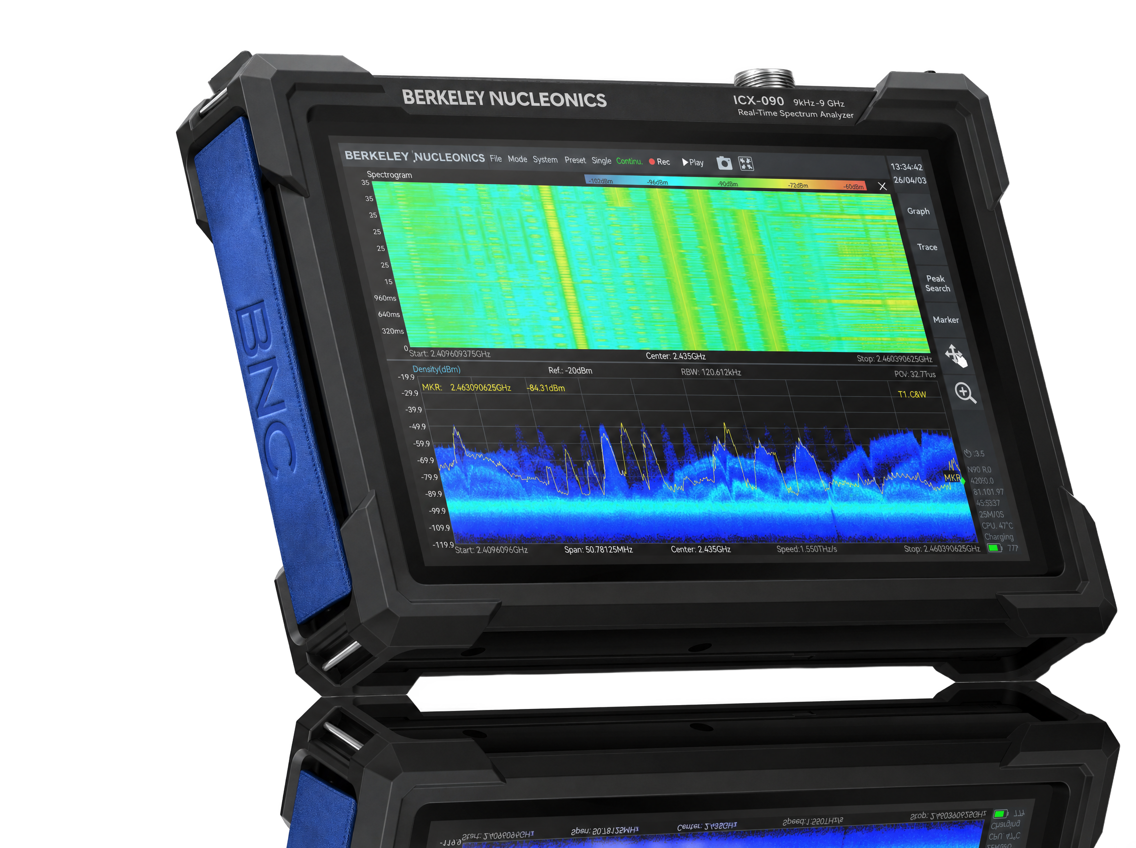 ICX-090 ICX-090 |
ICX-200 |
ICX-400 |
|---|---|---|---|
| Frequency range | 9 kHz to 9.5 GHz | 9 kHz to 20 GHz | 9 kHz to 40 GHz |
| Analysis bandwidth | 100 MHz | 100 MHz | 100 MHz |
| RF input connector | N (F), 50 Ω | 2.4 mm (M), 50 Ω | 2.4 mm (M), 50 Ω |
| Reference level range | -50 to +23 dBm (typ.) | -50 to +23 dBm (typ.) | -50 to +20 dBm (typ.) |
| Software/firmware | SpecICX-gen3 | SpecICX-gen3 | SpecICX-gen3 |
The wider ICX-FieldHawk catalog also includes the entry-tier ICX-045 and ICX-060. This summary details ICX-090, ICX-200, and ICX-400. verify ICX-045 and ICX-060 spec values against the published BNC datasheet.
4Operating Modes
SpecICX-gen3 provides seven main operating modes: Standard Spectrum Analysis, IQ Streaming, Power Detection Analysis, Real-Time Spectrum Analysis, Phase Noise Measurement, Digital Demodulation (option), and Harmonics Analysis.
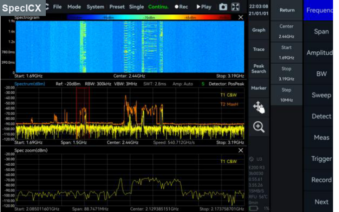
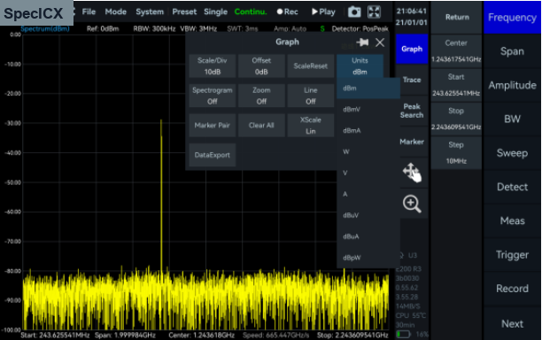
Standard Spectrum Analysis
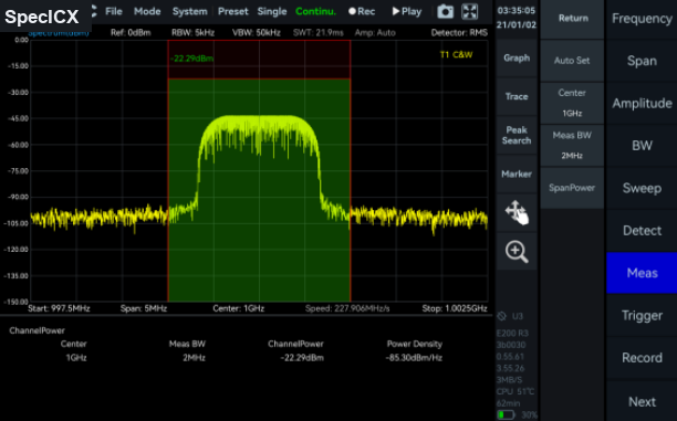
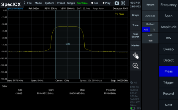
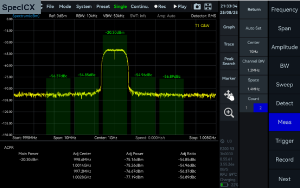
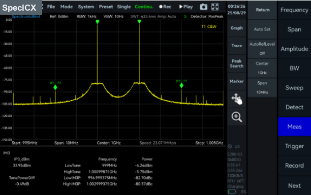
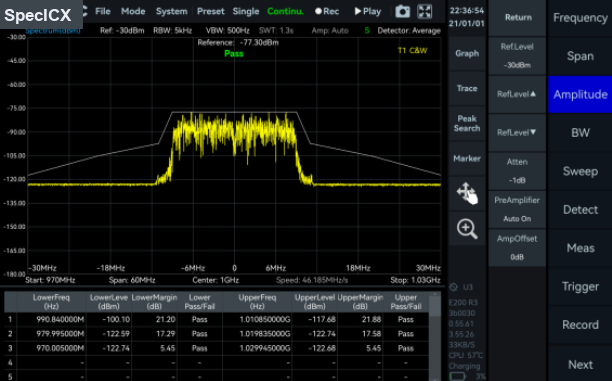
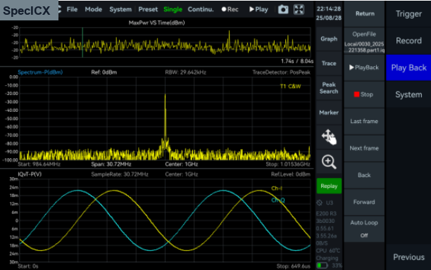
This mode provides a wide range of measurement functions, including full-span spectrum sweep, channel power, OBW, ACPR, IM3, and SEM. It also supports spectrum recording and playback. Combined with auxiliary tools such as signal tracking, peak table, and amplitude correction, it delivers a one-stop platform for comprehensive spectrum checks.
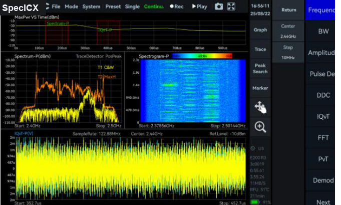
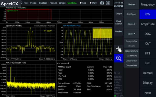
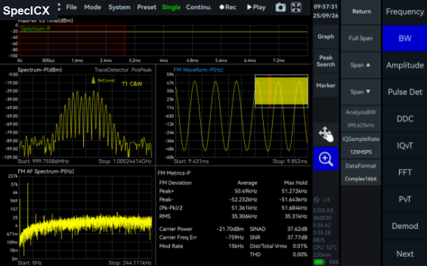
IQ Streaming
This mode supports up to 100 MHz analysis bandwidth and allows IQ data acquisition through multiple trigger methods. It provides IQ time-domain waveform display, spectrum and spectrogram views, AM and FM demodulation, and digital down conversion (DDC).
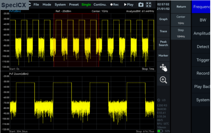
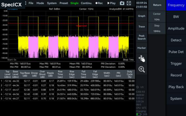
Power Detection Analysis
This mode enables detection and analysis of time-domain signals within the analysis bandwidth, making it suitable for applications focused on in-band power-versus-time relationships, such as pulse signal measurements.
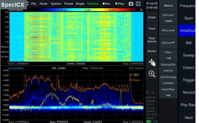
Real-Time Spectrum Analysis
This mode is powered by a high-speed FPGA-based FFT engine, featuring strictly gapless and overlap-free FFT, achieving true real-time monitoring across the full bandwidth.
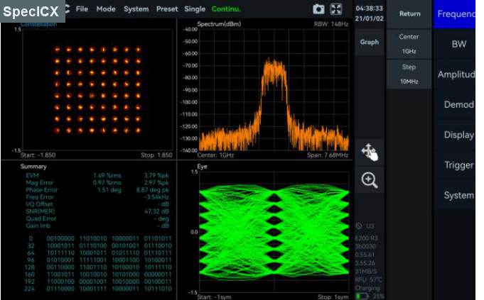
Digital Demodulation (option)
This mode supports 2ASK, 2FSK, 4FSK, GMSK, BPSK, QPSK, 8PSK, 16QAM, 64QAM, 128QAM, and 256QAM signals.
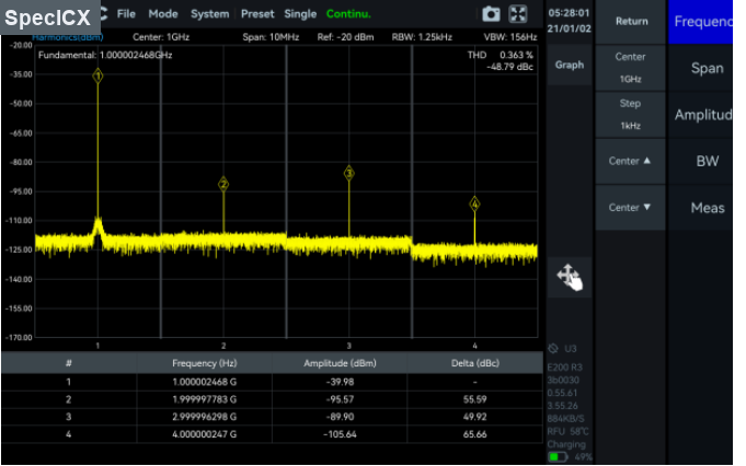
Harmonics Analysis
This mode supports detection and measurement of up to 10 harmonic components, including harmonic peaks, harmonic channel power, and total harmonic distortion.
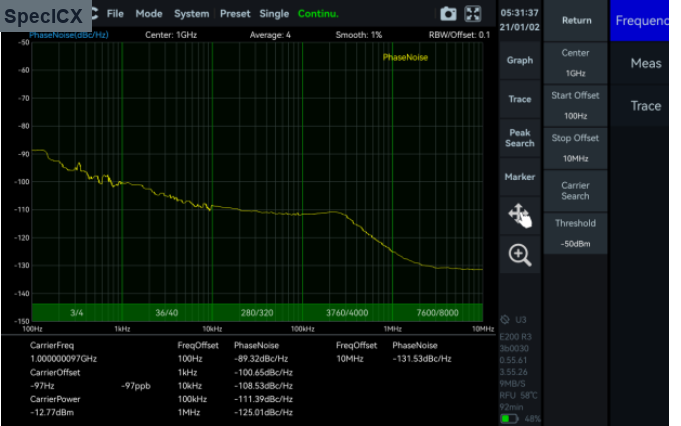
Phase Noise Measurement
This mode supports offset ranges from 1 Hz to 10 MHz for evaluating carrier phase stability. With the built-in automatic carrier search function, the software quickly locates the target carrier without manual adjustment.
5Measurement Functions
The standard measurement set covers the everyday RF tasks a field engineer reaches for, from channel power through demodulation and pulse detection. Each function is reachable from the touch interface and from the programmable API.
Power and Spectral Measurements
Demodulation
Correction and Workflow Tools
6Frequency
Three frequency reaches share the same handheld platform. Reference clock options and accuracy are common across the range.
| Frequency | ICX-090 |
ICX-200 |
ICX-400 |
|---|---|---|---|
| Frequency range | 9 kHz to 9.5 GHz | 9 kHz to 20 GHz | 9 kHz to 40 GHz |
| Reference clock | Internal or external | ||
| Frequency accuracy, TCXO (std.) | < 1 ppm, manual correction available | ||
| Frequency accuracy, OCXO (opt01) | < 1 ppm, manual correction available | ||
| Aging and temperature stability, TCXO (std.) | < 1 ppm/year, < 1 ppm | ||
| Aging and temperature stability, OCXO (opt01) | < 1 ppm/year, < 0.15 ppm | ||
7Spectrum Purity
SSB Phase Noise (dBc/Hz)
| Offset | ICX-090 |
ICX-200 |
ICX-400 |
|||
|---|---|---|---|---|---|---|
| Carrier frequency | 1 GHz | 9.5 GHz | 1 GHz | 20 GHz | 1 GHz | 40 GHz |
| 1 kHz | -95.2 | -91.5 | -91.2 | -80.6 | -99.0 | -78.4 |
| 10 kHz | -101.6 | -98.5 | -99.7 | -90.6 | -107.5 | -85.7 |
| 100 kHz | -100.6 | -99.7 | -101.1 | -96.2 | -107.7 | -85.1 |
| 1 MHz | -120.9 | -116.2 | -121.6 | -111.5 | -122.7 | -100.8 |
Residual Response (dBm)
Spur reject = bypass, RBW = 1 kHz, PosPeak detector.
| Band | ICX-090 |
ICX-200 |
ICX-400 |
|||
|---|---|---|---|---|---|---|
| Reference level (R.L.) | 0 dBm | -50 dBm | 0 dBm | -50 dBm | 0 dBm | -50 dBm |
| 9 kHz to 1 GHz | -83 | -120 | -90 | -120 | -72 | -103 |
| 1 GHz to 3 GHz | -83 | -120 | -80 | -120 | -72 | -103 |
| 3 GHz to 10 GHz | -90 | -130 | -90 | -120 | -72 | -103 |
| 10 GHz to 20 GHz | - | - | -90 | -120 | -91 | -115 |
| 20 GHz to 40 GHz | - | - | - | - | -85 | -105 |
IF Rejection (dBc), Typical
| Spur reject function | ICX-090 |
ICX-200 |
ICX-400 |
|||
|---|---|---|---|---|---|---|
| enhanced | bypass | enhanced | bypass | enhanced | bypass | |
| IF rejection | > 90 | > 80 | > 90 | > 80 | 8.2 to 21.75 GHz: > 68; other bands: > 90 | - |
Image Rejection (dBc), Typical
| Band | ICX-090 |
ICX-200 |
ICX-400 |
|||
|---|---|---|---|---|---|---|
| Spur reject function | standard | bypass | standard | bypass | standard | bypass |
| 90 MHz to 3 GHz | > 90 | > 76 | > 90 | > 79 | > 90 | - |
| 3 GHz to 9.5 GHz | > 90 | > 60 | > 90 | > 68 | > 90 | - |
| 9.5 GHz to 20 GHz | - | - | > 90 | > 60 | > 90 | - |
| 20 GHz to 33 GHz | - | - | - | - | > 90 | - |
| 33 GHz to 40 GHz | - | - | - | - | > 58 | - |
IIP3 / IIP2 (dBm)
| Reference level | ICX-090 |
ICX-200 |
ICX-400 |
|||
|---|---|---|---|---|---|---|
| Carrier frequency | 1 GHz | 9.5 GHz | 1 GHz | 20 GHz | 1 GHz | 40 GHz |
| R.L. = 20 dBm | 46.1 / 83.2 | 40.5 / 92.8 | 45.5 / 82.6 | 35.3 / 93.6 | 40.3 / 75.5 | 31.7 / 88.6 |
| R.L. = 0 dBm | 26.7 / 85.0 | 19.2 / 90.3 | 25.5 / 81.1 | 21.0 / 89.0 | 27.4 / 45.3 | 10.3 / 86.1 |
| R.L. = -20 dBm | 10.5 / 82.2 | 2.0 / 49.3 | 7.9 / 81.5 | -4.5 / 55.3 | 8.7 / 25.2 | 4.8 / 66.6 |
8Amplitude
| Parameter | ICX-090 / ICX-200 |
ICX-400 |
|---|---|---|
| Display range | DANL to 23 dBm (typ.) | DANL to 20 dBm (typ.) |
| Reference level (R.L.) | -50 dBm to +23 dBm (typ.) | -50 dBm to +20 dBm (typ.) |
| VSWR | 90 MHz to 9.5 / 20 GHz: < 2.0:1 | 90 MHz to 16 GHz: < 2.0:1; 16 GHz to 40 GHz: < 3.0:1 |
| Max. DC voltage | ± 10 VDC | |
| IF in-band flatness | ± 2.0 dB | |
| Max. input power (CW) | 23 dBm: 50 MHz to 9.5 / 20 / 40 GHz with preamplifier off; 10 dBm: 9 kHz to 50 MHz or preamplifier on | |
| Amplitude accuracy | 9 kHz to 9.5 GHz: ± 2.0 dB; 9.5 GHz to 20 / 40 GHz: ± 3.0 dB | |
| RF preamplifiers | Automatically turn on or forcibly turn off | |
9Display Average Noise Level
DANL in dBm/Hz, RBW = 1 kHz.
| Band | ICX-090 |
ICX-200 |
ICX-400 |
|||
|---|---|---|---|---|---|---|
| Reference level (R.L.) | -20 dBm | -50 dBm | -20 dBm | -50 dBm | -20 dBm | -50 dBm |
| 9 kHz to 1 MHz | -143.0 | -152.4 | -143.6 | -152.6 | -136.0 | -145.8 |
| 1 MHz to 90 MHz | -152.0 | -159.2 | -151.8 | -160.0 | -153.7 | -158.0 |
| 90 MHz to 3 GHz | -146.0 | -167.5 | -149.7 | -166.3 | -154.1 | -159.9 |
| 3 GHz to 9.5 GHz | -153.6 | -167.0 | -151.4 | -157.5 | -154.1 | -159.9 |
| 9.5 GHz to 19 GHz | - | - | -156.1 | -160.6 | -156.8 | -161.5 |
| 19 GHz to 20 GHz | - | - | -156.1 | -160.6 | -145.2 | -149.3 |
| 20 GHz to 40 GHz | - | - | - | - | -145.2 | -149.3 |
10Standard Spectrum Analysis
| Detector | PosPeak, NegPeak, Sample, Average, RMS, MaxPower |
| RBW | 1 Hz to 10 MHz |
| VBW | 1 Hz to 10 MHz |
| Data chart | SpecICX-gen3 provides spectrum, spectrogram, and historical trace |
| Measurements | Channel power, OBW, X dB bandwidth, adjacent channel power ratio, IM3 |
Sweep Speed
| RBW = 250 kHz, FPGA, spur reject = bypass | 1.0 THz/s |
| RBW = 250 kHz, FPGA, spur reject = standard | 577.5 GHz/s |
| RBW = 50 kHz, FPGA, spur reject = bypass | 212.6 GHz/s |
| RBW = 1 kHz, CPU, spur reject = bypass | 2.6 GHz/s |
Detection Analysis
| Lowest time resolution | 8 ns |
| Max. analysis bandwidth | 100 MHz |
| Detector | PosPeak, NegPeak, Sample, Average, RMS, MaxPower |
11IQ Recording
| Burst recording bandwidth | Maximum 100 MHz. Built-in memory depth is 128 Mbytes |
| Continuous recording bandwidth | Maximum 25 MHz |
| IQ sample rate | Maximum 125 MSPS; decimate factor 1, 2, 4, 8, 16, 32, 64, 128, 256, 512, 1024, 2048, 4096 |
| External trigger response | Maximum frequency response 500 times/s |
12Real-Time Spectrum Analysis
| FFT analysis | FFT engine is implemented in FPGA. Frame compression and trace detection are supported, with no missing samples between FFT frames. |
| FFT frame update rate | 109 ns / (N × D × 8 ns); POI = 2 × N × D × 8 ns. N is FFT points (2048, 1024, 512, 256, 128, 64, 32); D is the decimate factor (1, 2, 4, 8 and up). |
| Typical: N = 2048, D = 1 | FFT refresh rate 61,035 times/sec; POI 32.768 µs |
| Typical: N = 32, D = 1 | FFT refresh rate 3,906,250 times/sec; POI 0.512 µs |
| Max. analysis bandwidth | 100 MHz |
| Window function | B-Nuttall, Flat-top, LowSideLobe |
| RBW | 14.73 MHz to 3.59 kHz (Flat-top); 7.81 MHz to 1.90 kHz (B-Nuttall); 13 grades for each window type |
| Amplitude resolution | 0.75 dB |
13General & Interfaces
Input and Output
| Interface | ICX-090 / ICX-200 |
ICX-400 |
|---|---|---|
| RF input | N (F), impedance 50 Ω | 2.4 mm (M), impedance 50 Ω |
| Power | USB PD (65 W) | |
| USB port | USB 3.0 Type-C × 1, USB 2.0 Type-C × 1, USB 2.0 Type-A × 1 | |
| Audio interface | Micro HDMI × 1 (extended display support), 3.5 mm headphone port × 1 | |
| External reference clock input | MMCX (F), 10 MHz, amplitude ≥ 1.5 Vpp, impedance about 330 Ω | |
| Reference clock output | Integrated in AUXIO, 10 MHz, 3.3 V CMOS, programmable on/off | |
| External trigger input | MMCX (F), 3.3 V CMOS, high impedance | |
| Trigger output | MMCX (F), 3.3 V CMOS | |
| External antenna input | MMCX (F) | |
| Analog IF output | MMCX (F), -25 dBm max output power, impedance 50 Ω, 307.2 MHz ± 50 MHz | |
System and Environment
| Display | IPS LCD 1280 × 800, 10.1-inch multi-touch screen |
| RAM / EMMC storage | 4 GB / 32 GB |
| Power consumption | 25 W (typ.) |
| Size (D × W × H) | 260 × 179 × 46 mm |
| Weight | 1.5 kg |
| GNSS 1PPS synchronization accuracy | ± 100 ns, built-in GNSS (supports external antenna only) |
| Operating temperature (ambient) | 0 to 50 °C |
| Storage temperature (ambient) | -20 to +70 °C |
| Operating relative humidity | Ambient 0 to 40 °C: 5 to 75%; ambient above 40 °C: 5 to 45% |
| Packaging and accessories | Protected main unit × 1, power adapter × 1, power cord × 1, lanyard × 1 |
14Options & Accessories
Options
Functional upgrades to the analyzer. Each option is selected at order time.
| Code | Description | Type |
|---|---|---|
| OPT-010 | Built-in OCXO reference clock | Built-in hardware |
| OPT-410 | Basic digital demodulation | Software |
| OPT-420 | Pulse detection | Software |
Accessories
Antennas and physical add-ons. Antennas draw from the Berkeley Nucleonics antenna line.
| Accessory | Description | Type |
|---|---|---|
| ANT-100G | Directional antenna, 500 MHz to 10 GHz | Antenna accessory |
| ANT-200G | Directional antenna, 500 MHz to 20 GHz | Antenna accessory |
| Omnidirectional antenna | External omnidirectional antenna, 400 MHz to 8000 MHz, gain < 2 dBi | Antenna accessory |
15Test Conditions
Specifications apply under the following conditions:
- Start up and warm up for 10 minutes.
- Ambient temperature 25 °C (core temperature 50 °C).
- Standard spectrum analysis mode, spurious rejection standard on.
- Necessary heat dissipation is provided to keep ambient and core temperature within the rated range at the same time.
- Sweep speed and display average noise level test conditions: MCU 0.55.57, FPGA 0.55.22, API 0.55.61. verify firmware revision identifiers against the current SpecICX-gen3 release.
16Contact
For quotes, demonstrations, configuration help, and matched accessories such as the ANT-100G directional antenna, reach the Berkeley Nucleonics team.
Email: info@berkeleynucleonics.com
Phone: 800-234-7858