1Overview
The PCM-7700 series of air-cooled, high-power current sources is designed to drive laser diodes, bars, and arrays with up to 200 A of current at a load voltage of up to 25 V. Both models in the series deliver pulse widths from 500 µs to 50 ms and pulse repetition rates from single shot to 1 kHz.
Two variants cover different duty-cycle needs. The PCM-7700-48 includes a built-in power supply for a complete, self-contained bench unit. The PCM-7700-EX connects to an external supply, which lets the user run higher duty cycles where the application demands them. Directed Energy, Inc. is now a division of Berkeley Nucleonics, and the PCM-7700 ships from the same San Rafael, California build with one support path.
2How It Works
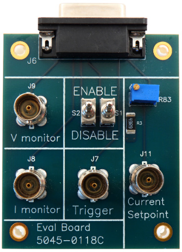
The PCM-7700 output current is set with a potentiometer on the included evaluation board or with an analog voltage. Pulse width is controlled by the trigger input, so the host system retains direct control over the shape and cadence of each pulse.
Two control modes are supported. In digital control mode, an input voltage sets the pulse output current and an external trigger signal sets the pulse width. In analog control mode, the output current follows the input voltage directly, which suits arbitrary current profiles driven from an external waveform source. In either mode, the instrument must always be operated within the safe operating area.
For automated test, complete control of the instrument is provided through a DB15 male connector, which carries the trigger, current setpoint, enable lines, and the current and voltage monitors.
3Specifications
The PCM-7700 current source meets or exceeds these specifications. All specifications are measured using the standard included output cable and an HPL-2400 low-inductance, high-power resistive load. The load is not included.
Pulse amplitude
| Parameter | Specification |
|---|---|
| Output current range | 5 A to 200 A1 |
| Setpoint resolution | 0.050 A |
| Setpoint accuracy | ± 1% of full scale current |
| Current overshoot | < 0.5% of full scale current |
| Current rise / fall time | ≤ 75 µs (with IOUT > 10 A) |
| Pulse width | 500 µs to 50 ms |
| Polarity | Positive |
| Load voltage (PCM-7700-48) | 0 V to 25 V2 |
| Load voltage (PCM-7700-EX) | 0 V to 25 V2 |
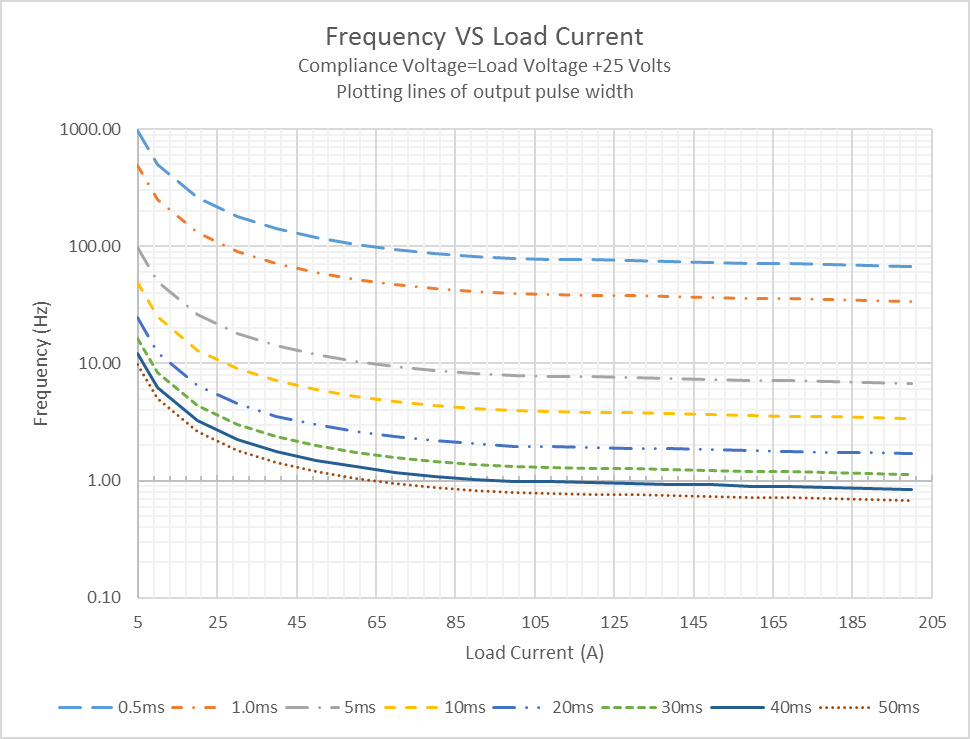
| Maximum output power | See SOA graphs |
Gate
| Parameter | Specification |
|---|---|
| Frequency range | Single shot to 1 kHz |
| Input voltage levels | 0 V: output OFF; 5 V: output ON |
| Gate pulse width | 500 µs to 50 ms (digital control mode); 0 to ∞ ms (analog control mode) |
| Termination impedance | 50 Ω |
| Connector | DB-15 pin 8 |
Current setpoint
| Parameter | Specification |
|---|---|
| Input voltage levels | 0 V to 10 V (0.000 V = 0 A output; 10.000 V = 200 A output) |
| Termination impedance | 10 kΩ |
| Response time on change | ≤ 5 µs |
| Connector | DB-15 pin 6 |
Enable signals
| Parameter | Specification |
|---|---|
| Input voltage levels | 0 V: enable; 5 V or open: disable |
| Termination impedance | 10 kΩ |
| Response time on change | ≤ 200 ms |
| Connector | DB-15 pin 4 (EXT ENABLE 1); DB-15 pin 3 (EXT ENABLE 2) |
Monitors
| Parameter | Specification |
|---|---|
| Current monitor | 5 mV/A (200 A output = 1.000 V typical) |
| Current monitor termination | 50 Ω |
| Current monitor connector | DB-15 pin 2 |
| Voltage monitor | 60 mV/V (30 V output = 1.800 V typical) |
| Voltage monitor termination | 1 MΩ |
| Voltage monitor connector | DB-15 pin 1 |
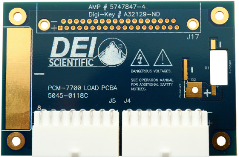
Output connector
| Parameter | Specification |
|---|---|
| Output connector | 2 x Amp 1-770974-0 (pins 1 through 8 = Out−; pins 9 through 16 = Out+) |
Power and general
| Parameter | Specification |
|---|---|
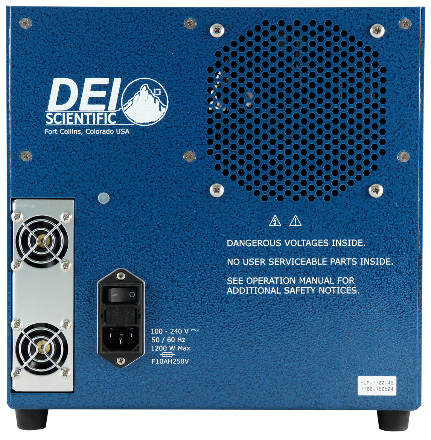
| Voltage requirements | 100 VAC to 240 VAC |
| Line frequency | 50 Hz to 60 Hz |
| Power requirements | PCM-7700-48: 1200 W; PCM-7700-EX: 250 W |
| Connector type | IEC 320-C14 |
| Size (H x W x D) | 27 cm x 27 cm x 39 cm |
| Weight | 15 kg |
| Operating temperature | 15 °C to 35 °C |
| Cooling | Air cooled (air flow from rear to front) |
4Output Protection & Safety
The PCM-7700 must be operated within its safe operating area at all times. The SOA defines the allowed combination of current, pulse width, and repetition rate that keeps the source and the connected diode within thermal and electrical limits. Separate SOA graphs apply to the PCM-7700-48 and the PCM-7700-EX, since the two variants differ in available duty cycle.
The dual enable lines give the host system a positive way to inhibit the output. Use the current and voltage monitors during setup to confirm the operating point before committing a sensitive diode load.
5Control & Interfaces
All control runs through a single DB15 male connector, which suits both bench operation from the evaluation board and integration into an automated test system.
| Function | DB-15 pin |
|---|---|
| Voltage monitor | Pin 1 |
| Current monitor | Pin 2 |
| EXT ENABLE 2 | Pin 3 |
| EXT ENABLE 1 | Pin 4 |
| Current setpoint | Pin 6 |
| Gate / trigger | Pin 8 |
Digital and analog control modes are both supported. In digital mode an input voltage sets the current and the trigger sets the width. In analog mode the output current tracks the input voltage, which allows arbitrary current shaping from an external waveform source.
6Applications
The PCM-7700 suits applications that need controlled, high-current pulses into low-impedance optical loads. Typical uses include:
- Laser diode bars and arrays. Up to 200 A into a 25 V load for QCW pumping and high-power diode drive.
- Pulsed pump sources. Long-pulse current delivery from 500 µs to 50 ms for solid-state laser pumping.
- Diode characterization. Repeatable current pulses with current and voltage monitors for device test and qualification.
- Higher duty-cycle test (PCM-7700-EX). External-supply operation where the application calls for sustained pulsing beyond the built-in supply.
7Ordering Information
| Part number | Description |
|---|---|
| PCM-7700-48 | Pulsed current source, internal power supply version |
| PCM-7700-EX | Pulsed current source, external power supply version (higher duty cycles) |
Contact
For a quote, configuration help, or application support, reach the Berkeley Nucleonics team.
Email: info@berkeleynucleonics.com
Phone: 800-234-7858