What the digital option adds
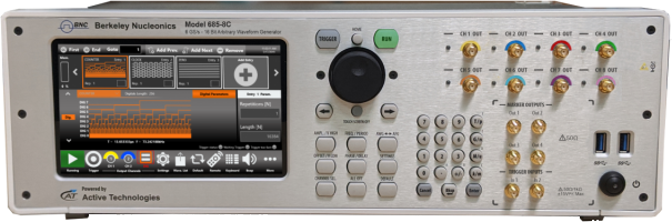
The digital option extends the BNC ArbRider series arbitrary waveform generators with eight high speed digital pattern outputs that play in lockstep with the analog channels. On the Model 670C, Model 675, and Model 685, those eight bits give you a synchronized digital bus alongside the analog waveforms, so a single instrument can drive a device under test with both its analog stimulus and the parallel digital control or data pattern that goes with it. The digital outputs are LVDS differential signals presented on a rear-panel mini-SAS HD connector, and they share the instrument timebase, so each digital edge stays aligned with the analog output rather than drifting against it.
The option is delivered as a software license key together with the RIDER-MINI-SAS-HD cable, a one meter cable that carries the eight LVDS pairs out of the instrument. The cable connector mates mechanically with standard mini-SAS HD hardware, but the electrical pinout is customized for the ArbRider series. Do not substitute a standard mini-SAS HD cable. The mechanical fit is identical, so a standard cable will seat without trouble, but the electrical connections differ and the unit will be damaged if a standard cable is used. Use only the cable supplied with the option.
Two accessories convert the LVDS bus into the signal standard your bench needs. Neither is included with the digital option, and each is ordered separately from the cable. The AT-LVDS-SMA8 is a mini-SAS to SMA adapter that breaks the eight LVDS outputs out to 16 SMA connectors, two SMA per LVDS pair. The AT-DTTL8 is a probe that connects to the supplied mini-SAS HD cable and converts the LVDS outputs to single-ended LVTTL signals.
Connecting to a custom board
If you connect the supplied mini-SAS HD cable to your own electronic board rather than to one of the BNC accessories, use a standard mini-SAS HD receptacle such as the Amphenol 10112626-101LF, Amphenol 10112632-101LF, Amphenol 10120666-101LF, or TE Connectivity 2198484-1. The mechanical mating is standard, but you must wire your board to the custom electrical pinout shown below rather than to the usual mini-SAS HD assignment. The pin map covers both the raw signal on each mini-SAS HD pin and the corresponding SMA on the AT-LVDS-SMA8 adapter.
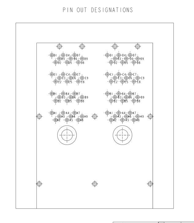
Mini-SAS HD connector pinout
The table lists each mini-SAS HD pin, the signal assigned to it, and the matching position on the AT-LVDS-SMA8 16-SMA breakout. Pins marked reserved must not be connected.
| Mini-SAS HD pin | Assigned signal | AT-LVDS-SMA8 (16 SMA) |
|---|---|---|
| A1 | +12 Vcc | NA |
| A2 | +12 Vcc | NA |
| A3 | GND | SMA Ground |
| A4 | DO7_P | DO 7_P |
| A5 | DO7_N | DO 7_N |
| A6 | GND | NA |
| A7 | DO0_P | DO 0_P |
| A8 | DO0_N | DO 0_N |
| A9 | GND | SMA Ground |
| B1 | CS1 (reserved, do not connect) | NA |
| B2 | +12 Vcc | NA |
| B3 | GND | SMA Ground |
| B4 | DO6_P | DO 6_P |
| B5 | DO6_N | DO 6_N |
| B6 | GND | SMA Ground |
| B7 | DO1_P | DO 1_P |
| B8 | DO1_N | DO 1_N |
| B9 | GND | SMA Ground |
| C1 | +5 Vcc | NA |
| C2 | +5 Vcc | NA |
| C3 | GND | SMA Ground |
| C4 | DO5_P | DO 5_P |
| C5 | DO5_N | DO 5_N |
| C6 | GND | SMA Ground |
| C7 | DO2_P | DO 2_P |
| C8 | DO2_N | DO 2_N |
| C9 | GND | SMA Ground |
| D1 | SCL (reserved, do not connect) | NA |
| D2 | SDA (reserved, do not connect) | NA |
| D3 | GND | SMA Ground |
| D4 | DO4_P | DO 4_P |
| D5 | DO4_N | DO 4_N |
| D6 | GND | SMA Ground |
| D7 | DO3_P | DO 3_P |
| D8 | DO3_N | DO 3_N |
| D9 | GND | SMA Ground |
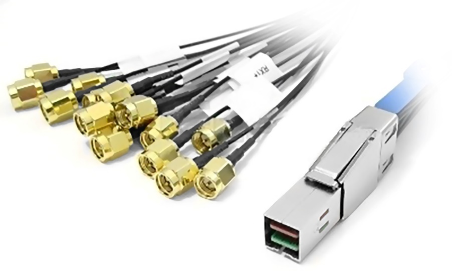
AT-LVDS-SMA8: LVDS to 16 SMA breakout
The AT-LVDS-SMA8 cable adapter converts the mini-SAS HD connector on the instrument rear panel to 16 SMA connectors. It preserves the signal integrity and gives the flexibility needed to route the high speed digital signals from the BNC ArbRider AWG series to individual coaxial inputs. Each of the eight LVDS pairs lands on two SMA connectors, one for the positive and one for the negative leg, so the full eight-bit bus is available as differential pairs across 16 SMA. The proprietary cable is one meter long.
| Parameter | Specification |
|---|---|
| Output connector | SMA |
| Output type | LVDS |
| Number of SMA | 16 (8 bits) |
| Cable type | Proprietary standard |
| Cable length | 1 meter (39.4 in) |
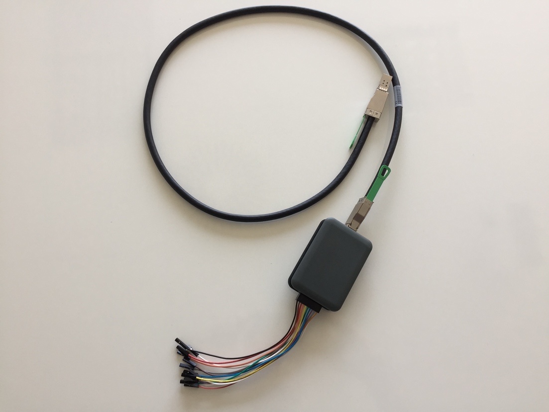
AT-DTTL8: LVDS to LVTTL probe
The AT-DTTL8 is an eight-bit LVDS-to-LVTTL adapter that converts the LVDS differential signals from the mini-SAS HD digital connector to standard single-ended LVTTL outputs. The probe lets you program the high-level voltage of the TTL signals from software, across a range of 0.8 V to 3.8 V into a high impedance load, with the same level applied to all channels. Maximum bit rate scales with the programmed level: 125 Mbps at 0.8 V and 400 Mbps at 3.8 V.
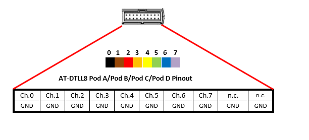
AT-DTTL8 output connector
The LVTTL signals are presented on a 20-position, 2.54 mm (0.1 in), two-row IDC header. Channels 0 through 7 occupy eight positions, each paired with a ground, and the two remaining positions are not connected.
| Parameter | Specification |
|---|---|
| Output connector | 20-position, 2.54 mm (0.1 in), 2-row IDC header |
| Output electrical standard | LVTTL |
| Output impedance | 50 Ω nominal |
| Output voltage | 0.8 V to 3.8 V programmable (same for all channels) |
| Maximum update rate | 125 Mbps at 0.8 V, 400 Mbps at 3.6 V |
| Dimensions | 2.05 in W × 0.87 in H × 2.99 in D (52 mm × 22 mm × 76 mm) |
| Input connector | Proprietary standard |
| Cable length | 1 meter (39.4 in) |
| Cable type | Proprietary |
Choosing the right output path
The decision comes down to the signal standard your device under test expects. If your inputs are coaxial and you want the native differential signaling with the best high speed integrity, take the LVDS bus straight out on the AT-LVDS-SMA8 and land each pair on its own SMA. If your device expects single-ended logic, the AT-DTTL8 gives you software-programmable LVTTL levels from 0.8 V to 3.8 V on a standard 0.1 in header, with bit rate that rises as you raise the level. In either case the eight digital bits stay synchronized to the analog channels through the shared instrument timebase, so the digital pattern and the analog stimulus play as one coordinated stimulus.
Talk to an application engineer
Berkeley Nucleonics can help you specify the digital option, the RIDER-MINI-SAS-HD cable, and the AT-LVDS-SMA8 or AT-DTTL8 accessory for your ArbRider 670C, 675, or 685 configuration. Call 800-234-7858 or email info@berkeleynucleonics.com.
For a quick question, chat with a BNC engineer (opens in a new window).