1Overview
The Berkeley Nucleonics Model A2085 is a two-channel arbitrary waveform generator built for circuit development, education, and production test. It outputs signals to 80 MHz, samples at up to 1.25 GS/s, and resolves amplitude to 14 bits, with frequency resolution down to 1 uHz. A built-in library of 152 standard and arbitrary waveforms, a complete modulation suite, and an integrated high-accuracy frequency counter let one instrument cover most everyday signal-generation tasks.
Operation is direct. An 8-inch, 800 by 600 pixel multi-touch screen presents waveform settings, modulation parameters, and counter readouts at a glance, and USB and LAN interfaces support transfer of user-defined waveforms and remote operation. The compact benchtop enclosure fits the crowded bench without crowding it.
Selecting for a new design. The Model A2085 is a long-established generator with a proven feature set. For new designs where there is a choice, Berkeley Nucleonics recommends the current high-speed models 685 and 686, which extend bandwidth and sample rate headroom. The A2085 remains a strong fit where its 80 MHz, 14-bit envelope and 8-inch touch interface match the task. Contact us to confirm the right model for your application.
2Key Features
- Two independent channels. Generate, modulate, and sequence signals on two outputs from a single instrument.
- 80 MHz output, 1.25 GS/s sampling. Sine output to 80 MHz with a 1.25 GSa/s sample rate and 1 uHz frequency resolution.
- 14-bit vertical resolution. Up to 1 M-point arbitrary waveform length for detailed, low-step signals.
- 152 built-in waveforms. Sine, square, pulse, ramp, noise, and harmonic, plus exponential rise and fall, sin(x)/x, step wave, and more, alongside user-defined arbitrary waveforms.
- Full modulation suite. AM, FM, PM, PWM, FSK, 3FSK, 4FSK, PSK, OSK, ASK, BPSK, sweep, and burst.
- Integrated frequency counter. High-accuracy counter spanning 100 mHz to 200 MHz with 7-digit resolution.
- 8-inch multi-touch display. 800 by 600 pixel touchscreen for fast, direct control.
- Low phase noise. -85 dBc/Hz at 1 GHz carrier with a 10 kHz offset.
5Amplitude & Offset
Amplitude
| Parameter | Specification |
|---|
| Into 50 ohm load | 1 mVpp to 10 Vpp (≤40 MHz); 1 mVpp to 5 Vpp (≤80 MHz); 1 mVpp to 2.5 Vpp (≤120 MHz); 1 mVpp to 1 Vpp (≤250 MHz) |
| Into open circuit or high-Z | 2 mVpp to 20 Vpp (≤40 MHz); 2 mVpp to 10 Vpp (≤80 MHz); 2 mVpp to 5 Vpp (≤120 MHz); 2 mVpp to 2 Vpp (≤250 MHz) |
| Accuracy | ±(1% of |setting| + 1 mVpp), typical, 1 kHz sine, 0 V offset |
| Resolution | 1 mV or 4 digits |
| Load impedance | 50 ohm (typical) |
DC Offset
| Parameter | Specification |
|---|
| Range (50 ohm) | ±(5 Vpk - Amplitude Vpp / 2) |
| Range (open circuit, high-Z) | ±(10 Vpk - Amplitude Vpp / 2) |
| Accuracy | ±(1% of |setting| + 1 mV + Amplitude Vpp x 0.5%) |
| Resolution | 1 mV or 4 digits |
6Sine Wave Spectral Purity
| Parameter | Specification |
|---|
| Harmonic distortion (typical, 0 dB) | DC to 1 MHz: < -65 dBc; 1 MHz to 10 MHz: < -60 dBc; 10 MHz to 120 MHz: < -50 dBc; 120 MHz to 250 MHz: < -45 dBc |
| Total harmonic distortion | < 0.05%, 10 Hz to 20 kHz, 1 Vpp |
| Spurious (non-harmonic, typical, 0 dB) | ≤10 MHz: < -70 dBc; >10 MHz: < -70 dBc + 6 dB/octave |
| Phase noise (typical, 0 dBm, 10 kHz deviation) | 10 MHz: ≤ -110 dBc/Hz |
7Square, Pulse, Ramp & Harmonic
Square
| Parameter | Specification |
|---|
| Rise / fall time | < 5 ns |
| Overshoot | < 3% |
| Duty cycle | 50.0% (fixed) |
| Jitter (rms) | 300 ps + 100 ppm |
Pulse
| Parameter | Specification |
|---|
| Pulse width | 12 ns to 996875 s |
| Rise / fall time | ≥ 7 ns |
| Overshoot | < 3% |
| Jitter (rms) | 300 ps + 100 ppm |
Ramp
| Parameter | Specification |
|---|
| Linearity | ≤ 1% of peak output (typical, 1 kHz, 1 Vpp, 50% symmetry) |
| Symmetry | 0% to 100% |
Harmonic
| Parameter | Specification |
|---|
| Harmonic order | ≤ 16 |
| Harmonic type | even, odd, all, user |
| Harmonic amplitude | Settable for all harmonics |
| Harmonic phase | Arbitrary |
8Arbitrary Waveform
| Parameter | Specification |
|---|
| Waveform length | 2 points to 1 M points |
| Vertical resolution | 14 bits |
| Minimum rise / fall time | < 7 ns |
| Jitter (rms) | 3 ns |
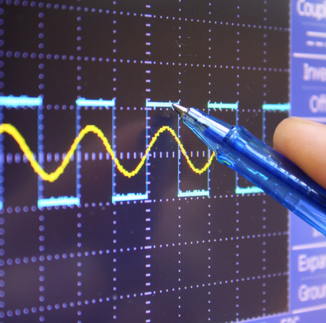
 Detailed arbitrary waveforms support electronic circuit debugging and bring-up, where defined edges and step sequences exercise a design under controlled conditions.
9Modulation
The Model A2085 supports a broad modulation set: AM, FM, PM, PWM, FSK, 3FSK, 4FSK, PSK, OSK, ASK, BPSK, sweep, and burst. The tables below detail the analog and digital modulation modes.
AM
| Parameter | Specification |
|---|
| Carrier waveform | sine, square, ramp, and arbitrary (except DC) |
| Source | internal / external |
| Modulating waveform | sine, square, ramp, noise, and arbitrary |
| Depth | 0.0% to 100.0% |
| Modulation frequency | 2 mHz to 100 kHz |
FM
| Parameter | Specification |
|---|
| Carrier waveform | sine, square, ramp, and arbitrary (except DC) |
| Source | internal / external |
| Modulating waveform | sine, square, ramp, noise, and arbitrary |
| Modulating frequency | 2 mHz to 100 kHz |
PM
| Parameter | Specification |
|---|
| Carrier waveform | sine, square, ramp, and arbitrary (except DC) |
| Source | internal / external |
| Modulating waveform | sine, square, ramp, noise, and arbitrary |
| Phase deviation | 0 to 180 degrees |
| Modulation frequency | 2 mHz to 100 kHz |
PWM
| Parameter | Specification |
|---|
| Carrier waveform | pulse |
| Source | internal / external |
| Modulating waveform | sine, square, ramp, noise, and arbitrary |
| Width deviation | 0 to minimum (pulse duty ratio, 100% - pulse duty ratio) |
| Modulating frequency | 2 mHz to 100 kHz |
FSK / 3FSK / 4FSK
| Parameter | Specification |
|---|
| Carrier waveform | sine, square, ramp, and arbitrary (except DC) |
| Source | internal / external |
| Modulating waveform | square with 50% duty cycle |
| Key frequency | 2 mHz to 1 MHz |
PSK
| Parameter | Specification |
|---|
| Carrier waveform | sine, square, ramp, and arbitrary (except DC) |
| Source | internal / external |
| Modulating waveform | square with 50% duty cycle |
| Key frequency | 2 mHz to 1 MHz |
OSK
| Parameter | Specification |
|---|
| Carrier waveform | sine, square, ramp, and arbitrary (except DC) |
| Source | internal |
| Oscillation time | square with 50% duty cycle |
| Key frequency | 2 mHz to 1 MHz |
ASK
| Parameter | Specification |
|---|
| Carrier waveform | sine, square, ramp, and arbitrary (except DC) |
| Source | internal / external |
| Modulating waveform | square with 50% duty cycle |
| Key frequency | 2 mHz to 1 MHz |
BPSK
| Parameter | Specification |
|---|
| Carrier waveform | sine, square, ramp, and arbitrary (except DC) |
| Source | internal |
| Modulating waveform | square with 50% duty cycle |
| Key frequency | 2 mHz to 1 MHz |
10Sweep & Burst
Sweep
| Parameter | Specification |
|---|
| Carrier waveform | sine, square, ramp, and arbitrary (except DC) |
| Type | linear and log |
| Sweep time | 1 ms to 500 s, ±0.1% |
| Trigger source | internal, external, and manual |
Burst
| Parameter | Specification |
|---|
| Carrier waveform | sine, square, ramp, pulse, and arbitrary (except DC) |
| Burst count | 1 to 50,000 period, infinite, gating |
| Internal period | 10 ns to 500 s |
| Gated source | external trigger |
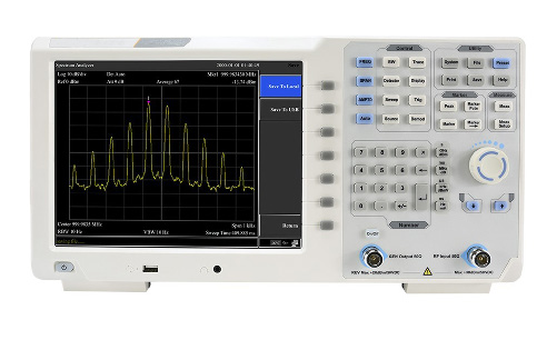 Sweep and burst modes pair naturally with bench measurement, letting an engineer characterize a circuit response across a frequency span or under gated stimulus.
11Frequency Counter
| Parameter | Specification |
|---|
| Function | frequency, period, +width, -width, +duty, and -duty |
| Frequency range | 100 mHz to 200 MHz |
| Frequency resolution | 7 digits |
12Display & I/O
| Parameter | Specification |
|---|
| Display | 8-inch, 800 by 600 pixel multi-touch LCD |
| I/O type | frequency counter; external modulation input; external trigger input; external reference clock input / output |
| Communication interface | USB Host, USB Device, and LAN |
13Applications
- Electronic circuit debugging. Drive and exercise designs with precise standard and arbitrary stimulus.
- Education and training. A clear touch interface and broad waveform library suit teaching labs.
- Circuit testing. Two channels and a full modulation suite cover functional and characterization test.
- Design and manufacture. Repeatable signals for development and production lines.
- Automobile maintenance and testing. Generate sensor and bus-style signals for diagnostics.
 From the teaching lab to systems-level design and manufacture, the Model A2085 supplies stimulus across a wide range of test environments.
14Software & Support
The Model A2085 operates standalone through its 8-inch multi-touch display, with USB Host, USB Device, and LAN interfaces for transferring user-defined waveforms and integrating the generator into a larger setup. External modulation, external trigger, and a reference clock input and output let the instrument synchronize with other equipment on the bench or rack.
Berkeley Nucleonics backs every instrument with US-based applications and service support. For configuration help, calibration, or integration questions, reach the team using the contacts below.
Request the full datasheet. For complete specifications, ordering details, and accessory options, request the full Model A2085 datasheet from Berkeley Nucleonics at
berkeleynucleonics.com/contact.