Introduction
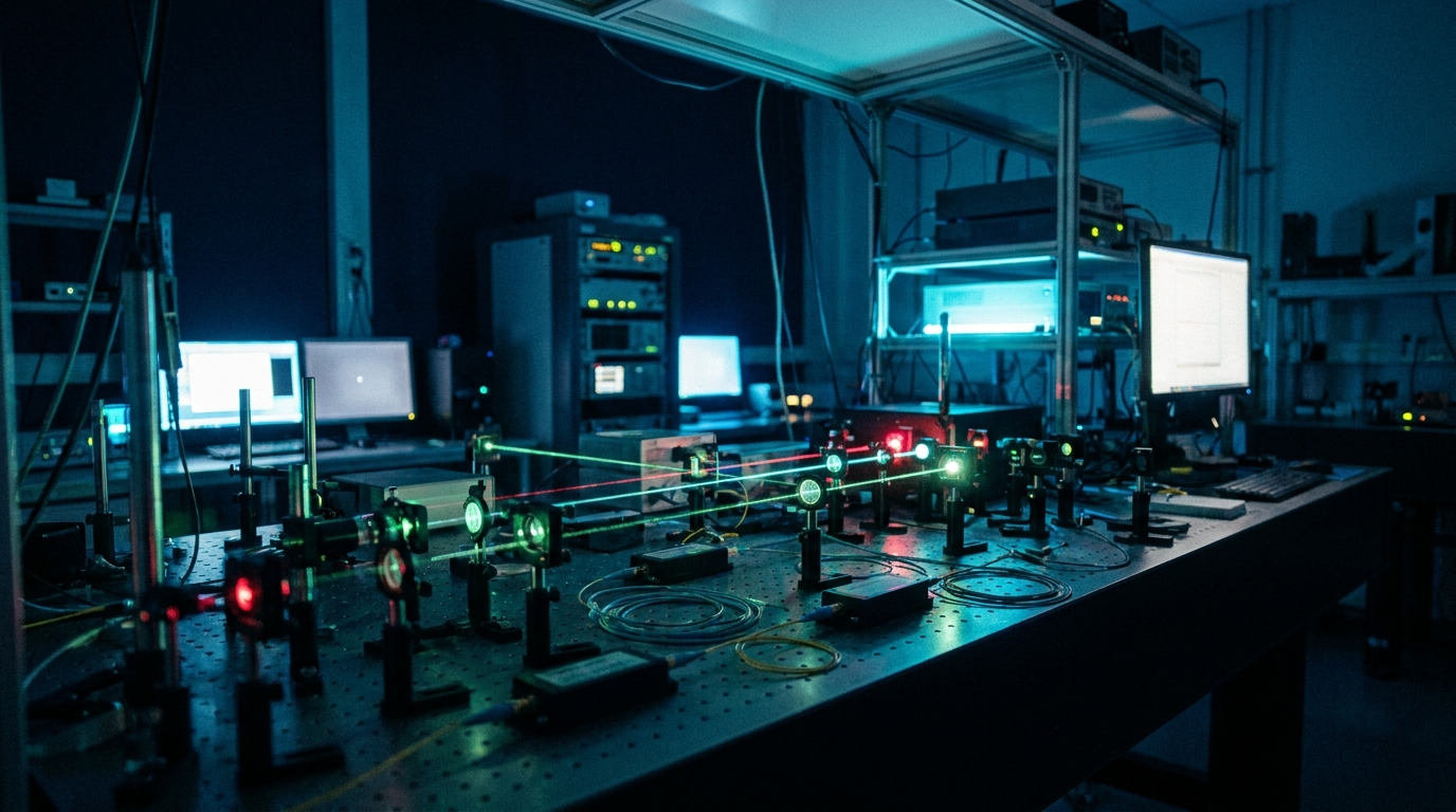
Applications built on optics, photonics, and lasers are now everywhere, and the newest generations of scientists keep opening fresh territory for them: LiDAR for automotive, medical instruments, aerospace and defense, quantum systems, and laser sensors. The testing challenges, the pressure to reach market quickly, and the increasingly demanding nature of these applications all point to the same answer. The modern arbitrary waveform and function generator is the right tool for the job.
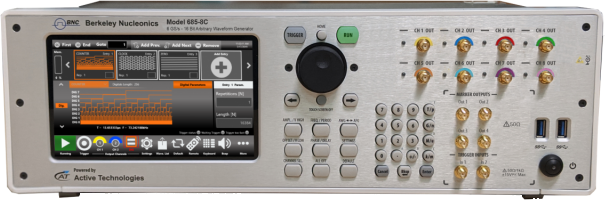
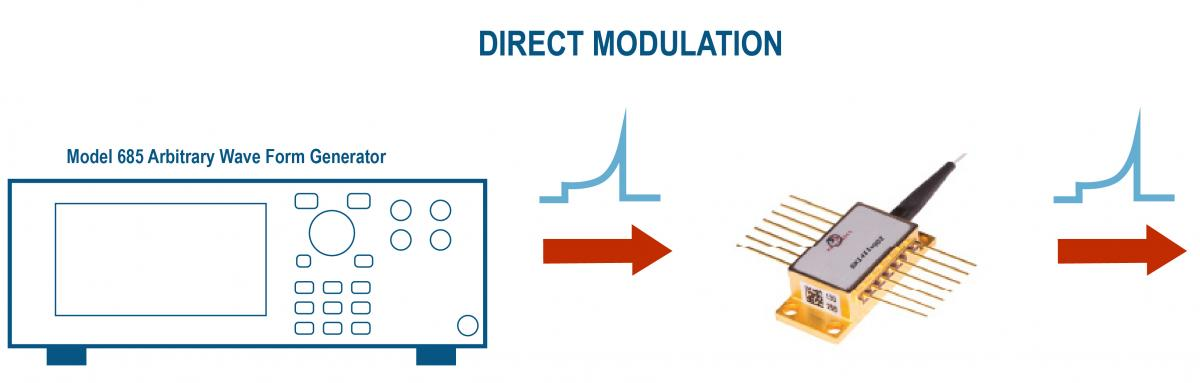
AWGs offer a kind of flexibility that was not available before. They give engineers one instrument that can produce nearly any pulse, signal, or modulation a setup calls for. The Model 685 Series targets the central problem in this space, which is generating clean, precisely shaped pulses for optics, photonics, and laser work. The result is an instrument that accelerates testing, reliability, and characterization of optics and photonics systems, and shortens the time it takes to produce the pulses and control signals that drive lasers and electro-optic modulators.
Different applications call for different signals. A few representative examples show the range the Model 685 covers:
- Electro-optic modulators. Generation of high-amplitude, high-speed pulses that drive electro-optic modulators directly.
- Quantum optics. Generation of varied signals and pulse sequences that serve as stimuli for quantum-optics experiments.
- Pulsed laser diodes. Generation of short, high-amplitude pulses that drive pulsed laser diodes.
Integrated-Optical Waveguides
Integrated-optical waveguides guide light along a defined path in a way that is analogous to optical fiber. The waveguide is a channel with a higher refractive index than the material around it.
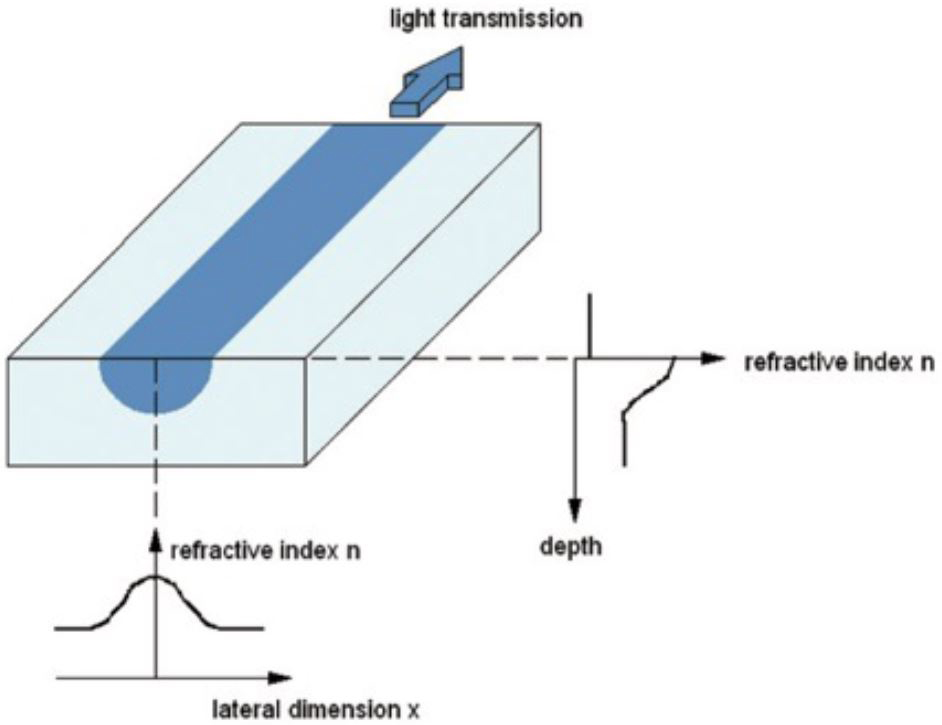
Light is held inside the channel by total internal reflection at its walls. Depending on the wavelength, the substrate refractive index, the index difference, and the width and depth of the channel, one or more transverse oscillation modes can be excited. Single-mode operation is of particular interest because it is essential to the function of many integrated-optical elements. In optical communication technology especially, these elements are usually supplied with optical fibers already attached.
The linear electro-optic effect, also called the Pockels effect, is a second-order nonlinear effect. It is the change in the refractive index of an optical material when an external electric field is applied. The amount of index change is proportional to the field strength, its direction, and the polarization of the light. The preferred material for integrated-optical modulators is lithium niobate (LiNbO3). When a field is applied to a waveguide through electrodes of length L, the refractive index changes in the region between the electrodes, which produces a phase shift in the guided light. That phase shift is linear in the applied voltage.
Phase and Amplitude Modulation
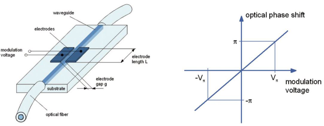
The voltage required typically amounts to a few volts. Longer wavelengths need a higher voltage than shorter ones for a given electrode geometry. For example, expect roughly 3 V in the red at 635 nm and about 10 V in the telecommunication range near 1550 nm. Because the electro-optic response is very fast, the control voltages are low, and the electrode geometry can be sophisticated, modulation at frequencies in the gigahertz range is achievable. Insert a phase modulator into an integrated Mach-Zehnder interferometer and you form an amplitude modulator.
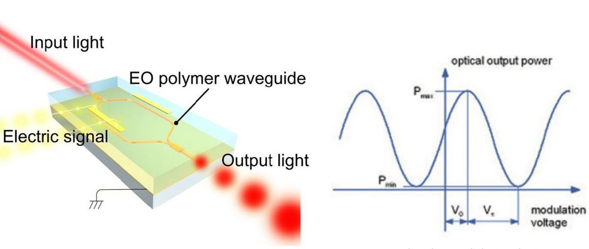
Applying a voltage creates a relative phase difference between the two branches, and interference then changes the output power at the device output. The transmission can be controlled between a minimum and a maximum value, from P min to P max. A relative phase difference of pi is needed to switch from the on state to the off state or back. The voltage that produces this is called the half-wave voltage, V pi, of the amplitude modulator. Because of push-pull operation, the half-wave voltage of an amplitude modulator is half that of a phase modulator with the same electrode length. As an example, expect about 1.5 V in the red at 635 nm and about 5 V in the telecommunication range near 1550 nm.
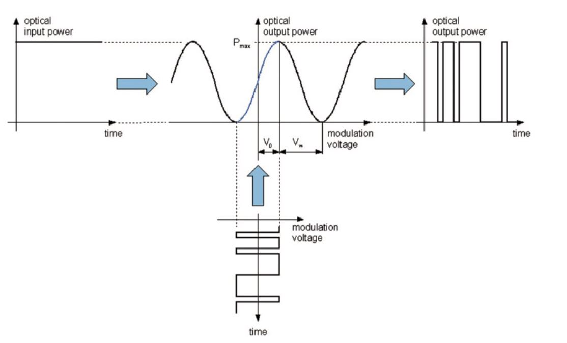
When an RF signal is applied to the electrodes as the modulation voltage, that electrical input is translated into amplitude information. The amplitude output depends on the magnitude and shape of the voltage, and therefore on where the modulator is biased on its characteristic curve. A binary pulsed electrical input maps to a binary optical output. If the voltage levels are wrong, meaning the voltage is too high or the offset is off, the modulator responds with incorrect optical levels in binary operation or with higher harmonics in analog operation.
Driving Modulators with the Model 685
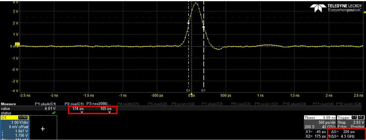
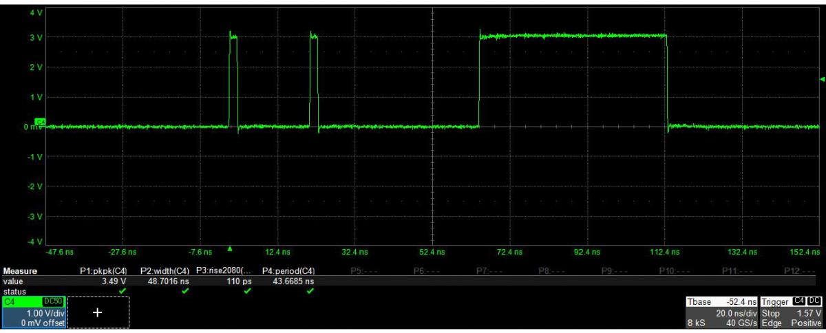
The Model 685 arbitrary waveform generators let you create the modulation voltage by generating very narrow pulses, with a minimum pulse width of 230 ps, at amplitudes up to 5 Vpp. That high-amplitude output, combined with 110 ps rise and fall time at 5 Vpp into a 2 GHz bandwidth, lets you drive many types of electro-optic modulators directly, with no external amplifier in the path.
Through the True-Arb user interface, you can build a wide range of pulse shapes, which gives finer control over the optical output signal.
Quantum Optics
Color centers in diamond are defects in the crystal lattice, where carbon atoms are replaced by other kinds of atoms and adjacent lattice sites are left empty. Because of their bright single-photon emission and optically accessible spins, color centers are promising solid-state quantum emitters for future quantum information processing and quantum networks. Two of the most mature systems for entangling spin qubits with coherent photons are quantum dots and the nitrogen-vacancy (NV) center in diamond. NV centers show excellent coherence times, exceeding 1 s, but they lack efficient emission into the zero-phonon line (ZPL) needed to yield indistinguishable photons. Quantum dots show strong emission properties but are limited to coherence times of tens of nanoseconds. That contrast captures the usual challenge of working with solid-state quantum emitters: getting good single-photon generation and long emitter spin coherence times at the same time.
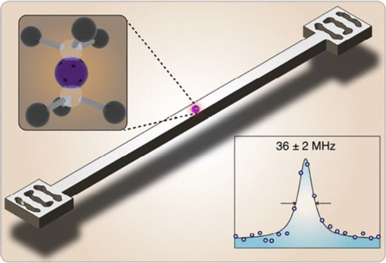
Recent work on group IV vacancy centers in diamond, in particular SiV centers, shows promising results against both goals. Combined with their favorable spin properties, tin-based vacancy centers are well suited to nanophotonic platforms because of their strong, stable zero-phonon-line emission in nanostructures. Group IV vacancy centers show excellent optical properties thanks to a crystallographic symmetry that favors emission into the ZPL. SiV centers show 10 ms coherence times at 100 mK, and SnV is predicted to reach similar times at 2 K, a temperature that standard helium cryostats reach easily.
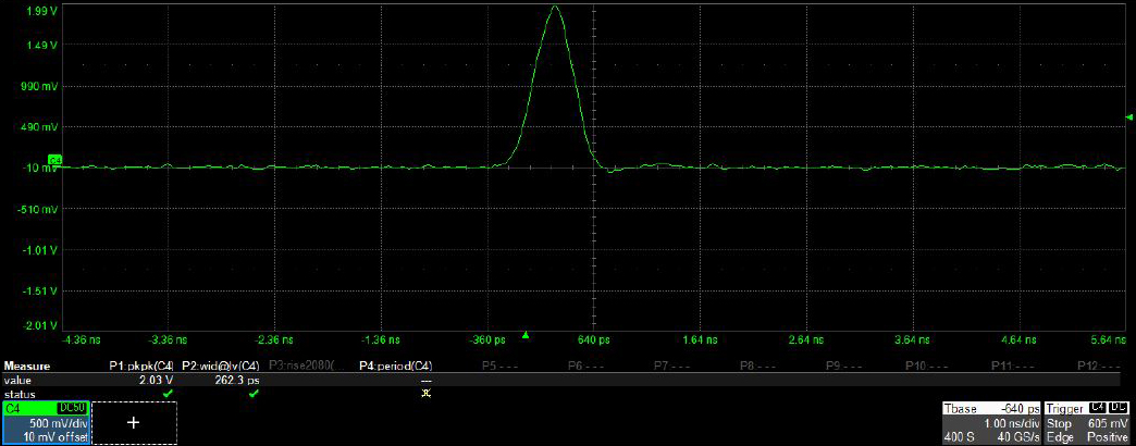
The Model 685 Series has been used to control the pulse sequences that manipulate single tin-vacancy centers in diamond. The instrument generates narrow electrical square pulses with high amplitude, greater than 1.5 V, to control an electro-optic amplitude modulator and produce short laser pulses. With this method, optical pulses with a close-to-Gaussian shape and a full-width-half-maximum as narrow as 280 ps are possible. The Model 685 has also been used to drive an electro-optic phase modulator for generation of frequency sidebands up to about 2 GHz, which enables driving two optical transitions with phase-stable laser fields.
The digital output channels of the Model 685 can control acousto-optic amplitude modulators, or they can generate trigger pulses for the timing of experimental sequences. Looking ahead, these experiments will increasingly require real-time control of measurement protocols, where the next step depends on the outcome of a readout earlier in the sequence.
Pulsed Laser Diode Driving
The ability of pulsed laser diodes to deliver short pulses of intense power has made them an ideal choice for military applications such as target designation and rangefinding. Much of the early motivation for developing these diodes was in fact military. Today, improvements in technology and reductions in cost are opening new uses in metrology and medicine.
Continuous versus pulsed operation
Standard laser diodes are built to emit continuous-wave radiation, with power from a few milliwatts to a few watts. A pulsed laser runs at a lower duty cycle, so heat removal is less of a concern. A pulsed laser's output facet also generally has much lower reflectivity than a CW device. On typical CW lasers, threshold is kept low by limiting the emitting width to 5 to 35 microns. Threshold current is directly proportional to that width, but the high gain in pulsed lasers allows the width to grow up to 400 microns, with a matching increase in peak power.
Pulsed laser diodes are designed to be driven with high-current pulses that produce short, high-power optical pulses. To reach the very high peak powers most applications need, the duty cycle is usually kept below 0.1 percent. That means a 100 ns optical pulse is followed by a pause of 100 microseconds, so very short pulses are available at repetition rates in the kilohertz range. Maximum pulse lengths are typically around 200 ns, with 3 to 50 ns pulses being more common. Creating these optical pulses takes currents on the order of several tens of amperes, which requires fast switching transistors and careful circuitry, with every electrical connection kept as short as possible to reduce inductive losses.
The first commercial GaAs pulsed lasers emitted at 905 nm. That wavelength sits close to the peak responsivity of silicon detectors and near a water absorption peak, which reduces ambient light and increases detection sensitivity. As new semiconductor materials arrived, a wider range of wavelengths became feasible. Lasers in the 1550 nm range have drawn more attention for their better transmission through fog and smoke, and because that wavelength is less hazardous to vision than shorter ones.
Time of flight and other functions
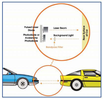
Many pulsed-laser-diode applications are variants of the original rangefinding application, in which target distance is found by measuring the flight time of a laser pulse reflected or backscattered from the target. With this principle, the more sophisticated instruments can measure accurately at distances up to 10 km. Police laser speed guns, for example, can measure vehicle speed up to 155 mph at up to 3,300 ft with an accuracy of 1 to 3 percent. Unlike RF speed guns, which read velocity directly from the Doppler shift, laser speed guns calculate velocity by comparing distance measurements taken at different times. As prices fell, eye-safe rangefinders became available for recreational uses, from hunting to golf.
Pulsed laser diodes supply the optical signal in automotive collision-avoidance systems, serve as navigational aids for ships in ports and harbors, appear in ceilometers for cloud-base measurement at airports, and support surveying and construction. In a laser safety scanner, pulsed laser diodes form a curtain of light around hazardous areas such as automated production lines, and coded pulse emission lets a two-dimensional curtain distinguish allowed from disallowed shapes. The high peak power from pulsed laser diodes, paired with avalanche photodiodes, gives the sensitivity needed to tell shapes apart. There is also significant research into the wound-healing ability of pulsed laser diodes in medical uses such as laser acupuncture and therapy, where wavelengths from 625 to 905 nm are favored.
Generating short, powerful pulses with laser diodes is an enabling technology for a range of applications that CW laser diodes cannot address, for technical or economic reasons. The Model 685 can drive the pulsed laser diode directly, or drive it indirectly through an electro-optic or acousto-optic modulator.
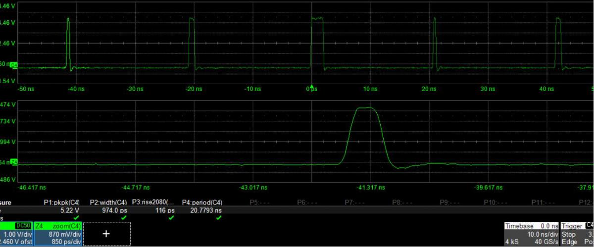
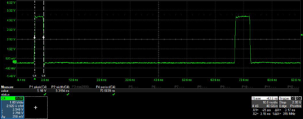
Pulsed laser diodes need to be driven with high-amplitude, very short, narrow pulses. The Model 685 can create rectangular, Gaussian, and exponential pulse shapes with amplitude up to 5 Vpp, 110 ps rise and fall time, and a minimum pulse width of 230 ps. The screenshots below show how easily the different pulses are built in the True-Arb interface and then reproduced on an oscilloscope.
Conclusion
The Model 685 Series provides an extremely flexible, high-performance way to generate the full range of pulses and signals that today's challenges in quantum optics, photonics, and laser applications demand. As industry requirements grow and new products arrive, the demand for cutting-edge test instrumentation rises with them, both to satisfy the most demanding applications and to keep pace with the latest ideas coming out of the lab.
Talk to an application engineer
Berkeley Nucleonics can help you match a Model 685 Series configuration to your optics, photonics, or laser setup. Call 800-234-7858 or email info@berkeleynucleonics.com.
For a quick question, chat with an engineer at berkeleynucleonics.com.