1Overview
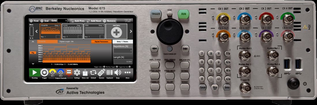
The Berkeley Nucleonics Model 675 is a simple-to-use arbitrary waveform generator that runs on Windows 10 through an intuitive proprietary GUI. The interface can be driven from the integrated touchscreen or remotely over a standard Ethernet connection, so the instrument fits the bench and the automated test rack equally well.
The Model 675 pairs a 1.2 GS/s sample rate with 16-bit vertical resolution and offers 2, 4, or 8 analog channels delivering up to 12 Vp-p into a 50 ohm load. A 32-channel digital output option is available, with each digital line running up to 1.2 Gb/s in LVDS format. Rise and fall times under 2 ns keep signal integrity high across the operating range.
Digital output, combined and synchronized with the analog signals, makes the Model 675 an effective diagnostic tool for digital designs. The instrument can produce waveforms up to 1024 Mpoints per channel, combined with up to 16,384 sequence entries and up to 4,294,967,294 repetitions, which suits it to the most demanding technical applications.
2Key Features
- 2, 4, or 8 analog channels. Scale the channel count to the test, from a two-channel bench unit to an eight-channel multi-signal source.
- 1.2 GS/s, 16-bit resolution. Sample rates from 1 S/s to 1.2 GS/s with 16-bit vertical resolution for excellent signal fidelity.
- 318 MHz calculated bandwidth. Fast edges with rise and fall time at or below 1.1 ns in True Arb mode give a calculated bandwidth at or above 318 MHz.
- One software, three roles. The Rider environment switches the instrument between arbitrary-waveform (True Arb), function-generator (AFG), and serial pattern (DPG) modes without changing hardware.
- Deep waveform memory. Up to 1024 Mpoints per channel, with up to 16,384 sequence entries and up to 4,294,967,294 repetitions.
- High output and offset. Up to 24 Vp-p output and up to plus or minus 12 V hardware baseline offset with the high-voltage option.
- Synchronized digital generation. Up to 32 digital channels generated in sync with the analog waveforms, each running up to 1.2 Gb/s in LVDS.
- Touch and remote control. A 7-inch capacitive touchscreen on Windows 10, with a standard Ethernet interface for remote operation and automation.
3Hardware & Interfaces
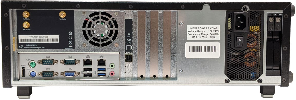
Analog outputs use front-panel BNC connectors. Reference clock, external modulation, and digital pod connections sit on the rear panel, alongside the AC inlet, Ethernet, USB 3.0, and standard PC peripheral ports. The instrument is a 3U 19-inch rackmount unit that also runs comfortably on the bench.
4User Interface & Modes
The Model 675 user interface is designed for touch. It puts the capabilities of a modern waveform generator within reach through a layout that recalls the simplicity of tablets and smartphones. Swipe gestures, a touch-friendly virtual keypad, time-saving shortcuts, and clear icons let engineers and scientists build advanced waveforms or digital patterns in a few touches.
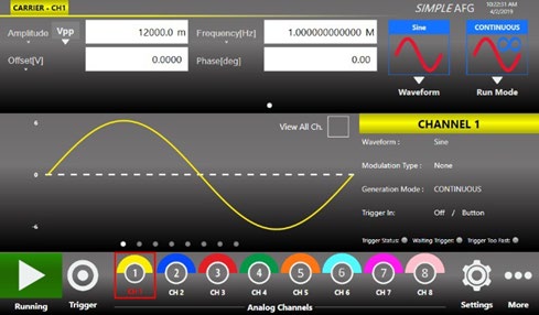
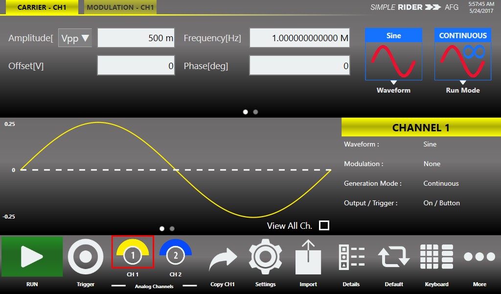
Simple Rider AFG: Function Generator mode
In function-generator mode, the swipe gesture exposes the output waveform parameters, the virtual numeric keypad speeds data entry, and intuitive icons simplify instrument setup. Standard waveforms, run modes, and modulation are all a touch away.
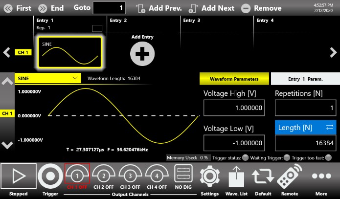
Simple Rider True Arb: AWG and DPG mode
In True Arb, users define complex waveforms with up to 16,384 sequence entries of analog waveforms and digital patterns, then set the execution flow with loops, jumps, and conditional branches. Digital output combined and synchronized with analog signals provides an effective way to troubleshoot and validate digital designs. With waveform memory up to 1 GSample per channel and up to 4,294,967,294 repetitions, the most complex waveform scenarios can be created with a few screen touches.
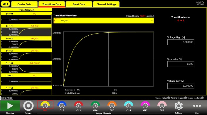
Simple Rider SPG: Serial Pattern Generator mode
The serial pattern generator interface creates pattern scenarios in a few screen touches. It generates PRBS patterns and custom patterns up to 2 MSymbols where bit transitions can take arbitrarily user-defined shapes, at rates up to 300 Mbaud. The software architecture supports different generation modes and can modulate patterns with internal or external signals to reproduce noise effects such as jitter and ripple.
5General Specifications
All specifications are typical unless noted otherwise. Guaranteed performance refers to a calibrated instrument stored for a minimum of 2 hours within the operating temperature range of 5 C to 40 C and after a 45-minute warm-up, within plus or minus 10 C after auto-calibration.
| Parameter | Model 675-2C | Model 675-4C | Model 675-8C |
|---|---|---|---|
| Analog channels | 2 | 4 | 8 |
| Digital out (optional) | 0 / 8 | 0 / 8 / 16 | 0 / 8 / 16 / 32 |
| Marker out | 1 | 2 | 4 |
| Parameter | Specification |
|---|---|
| Operating modes | AFG mode, True Arb mode, Serial Pattern Generator (optional) |
| Amplitude range (50 ohm into 50 ohm)1 | 0 to 6 Vp-p (12 Vp-p optional) |
| Amplitude accuracy (guaranteed, 1 kHz sine, 0 V offset, >5 mVp-p, 50 ohm) | plus or minus (1% of setting [Vp-p] + 5 mV) |
| Amplitude resolution | Less than 0.5 mVp-p or 5 digits |
| Output impedance | Single-ended 50 ohm; low impedance 5 ohm |
| Baseline offset range (50 ohm into 50 ohm) | -3 V to +3 V (-6 V to +6 V optional) |
| Baseline offset range (50 ohm into high-Z load) | -6 V to +6 V (-12 V to +12 V optional) |
| Baseline offset accuracy (guaranteed, 50 ohm into 50 ohm) | plus or minus (1% of |setting| plus or minus 5 mV) |
| Baseline offset resolution | Less than 4 mV or 4 digits |
| DC amplitude range (50 ohm, single-ended) | -3 V to 3 V (-6 V to 6 V optional) |
| DC amplitude accuracy (guaranteed) | plus or minus (1% of |setting| + 10 mV) |
6Function Generator (AFG) Mode
| Parameter | Specification |
|---|---|
| Connectors | BNC on front panel |
| Output type | Single-ended |
| Output impedance | 50 ohm or 5 ohm (low impedance) |
| Operating mode | DDS mode |
| Standard waveforms | Sine, Square, Pulse, Ramp, and more (Noise, DC, Sin(x)/x, Gaussian, Lorentz, Exponential Rise, Exponential Decay, Haversine) |
| Run modes | Continuous, modulation, sweep, burst |
| Arbitrary waveforms | 16-bit vertical resolution; waveform length 16,384 points |
| Internal trigger timer range | 13.3 ns to 100 s |
| Internal trigger timer resolution | 104 ps |
| Internal trigger timer accuracy | plus or minus (0.1% setting + 5 ps) |
7Standard Waveforms
Sine waves
| Parameter | Specification |
|---|---|
| Frequency range (50 ohm into 50 ohm)2 | 1 uHz to 70 MHz: 12 V; >70 to 120 MHz: 9 V; >120 to 180 MHz: 6 V; >180 to 300 MHz: 3 V |
| Flatness (1 Vp-p, relative to 1 kHz) | DC to 300 MHz: plus or minus 0.5 dB |
| Harmonic distortion (1 Vp-p) | 1 uHz to 10 MHz: < -65 dBc; >10 to 50 MHz: < -55 dBc; >50 to 100 MHz: < -45 dBc; >100 to 300 MHz: < -30 dBc |
| Total harmonic distortion (1 Vp-p) | 10 Hz to 20 kHz: < 0.1% |
| Spurious (1 Vp-p) | 1 uHz to 10 MHz: < -60 dBc; >10 to 300 MHz: < -55 dBc |
| Phase noise (1 Vp-p, 10 kHz offset) | 10 MHz: < -120 dBc/Hz typ.; 100 MHz: < -115 dBc/Hz typ. |
Square waves
| Parameter | Specification |
|---|---|
| Frequency range | 1 uHz to 40 MHz: 12 V; >40 to 80 MHz: 10 V; >80 to 150 MHz: 7 V |
| Rise/fall time | 2 ns |
| Overshoot (1 Vp-p) | < 2% |
| Jitter (rms) | < 20 ps |
Pulse waves
| Parameter | Specification |
|---|---|
| Frequency range | 1 uHz to 5 MHz: 12 V; >5 to 60 MHz: 10 V; >60 to 150 MHz: 7 V |
| Pulse width | 2.5 ns to (Period - 2.5 ns) |
| Pulse width resolution | 20 ps or 15 digits |
| Pulse duty cycle | 0% to 100%, 14 digits (pulse width limitations apply) |
| Leading/trailing edge transition time | 2 ns to 1000 s |
| Transition time resolution | 2 ps or 15 digits |
| Overshoot (1 Vp-p) | < 2% |
| Jitter (rms, rise and fall time at or above 2 ns) | < 20 ps |
Double pulse, ramp, and other waves
| Parameter | Specification |
|---|---|
| Double pulse range (without HV option) | 1 uHz to 5 MHz: 12 Vp-p; >5 to 150 MHz: 6 Vp-p, where Vp-p = |Vp-p 1| + |Vp-p 2| |
| Double pulse range (with HV option) | 1 uHz to 5 MHz: 24 Vp-p; >5 to 60 MHz: 10 Vp-p; >60 to 150 MHz: 7 Vp-p |
| Ramp frequency range | 1 uHz to 15 MHz |
| Ramp linearity (<10 kHz, 1 Vp-p, 100%) | at or below 0.1% |
| Ramp symmetry | 0% to 100% |
| Exponential Rise / Decay frequency range | 1 uHz to 15 MHz |
| Sin(x)/x, Gaussian, Lorentz, Haversine frequency range | 1 uHz to 30 MHz |
| Additive noise bandwidth (-3 dB) | > 200 MHz |
| Additive noise level | 0 V to 6 V minus |carrier max value [Vpk]| |
| Additive noise resolution | 1 mV |
| Arbitrary number of samples | 2 to 16,384 |
| Arbitrary frequency range | 1 uHz to 150 MHz |
| Arbitrary analog bandwidth (-3 dB) | 175 MHz |
| Frequency resolution (sine, square, pulse, arbitrary, Sin(x)/x) | 1 uHz or 15 digits |
| Frequency accuracy (non-ARB) | plus or minus 2.0 x 10⁻⁶ of setting |
| Frequency accuracy (ARB) | plus or minus 2.0 x 10⁻⁶ of setting plus or minus 1 uHz |
8Modulation, Sweep & Burst
The Model 675 supports amplitude, frequency, phase, and pulse-width modulation, frequency-shift and phase-shift keying, linear and logarithmic sweep, and triggered or gated burst. Modulation can be sourced internally or externally.
| Parameter | Specification |
|---|---|
| AM / FM / PM carrier waveforms | Standard waveforms (except Pulse, DC, and Noise), ARB |
| Modulation source | Internal or external |
| Internal modulating waveforms (AM/FM/PM) | Sine, Square, Ramp, Noise, ARB |
| Modulating frequency | Internal: 500 uHz to 48 MHz; External: 8 MHz maximum |
| AM depth | 0.00% to 120.00% |
| FM peak deviation | DC to 300 MHz |
| PM phase deviation range | 0 deg to 360 deg |
| FSK hop frequency / number of keys | 1 uHz to 300 MHz / 2 |
| PSK hop phase / number of keys | 0 deg to +360 deg / 2 |
| PWM carrier / deviation range | Pulse / 0% to 50% of pulse period |
| Sweep type | Linear, logarithmic, staircase, and user defined |
| Sweep time | 40 ns to 2000 s |
| Total sweep time accuracy | at or below 0.4% |
| Sweep start/stop frequency range | Sine: 1 uHz to 300 MHz; Square: 1 uHz to 150 MHz |
| Burst waveforms / type | Standard waveforms (except DC and Noise), ARB / trigger or gated |
| Burst count | 1 to 4,294,967,295 cycles or infinite |
9True Arb Mode
| Parameter | Specification |
|---|---|
| Connectors / output type | BNC on front panel / single-ended |
| Output impedance | 50 ohm or 5 ohm (low impedance) |
| Operating mode | Variable clock (True Arbitrary) |
| Run modes | Continuous, Triggered Continuous, Single/Burst, Stepped, Advanced |
| Vertical resolution | 16 bit |
| Waveform length | 16 to 2M samples (675-XC-2M); 16 to 64M (675-XC-64M); 16 to 128M (675-XC-128M); 16 to 1024M (675-XC-1G), where X = 2, 4, or 8 |
| Waveform granularity | 1 if entry length > 384 samples; 16 if entry length is 32 to 384 samples |
| Sequence length | 1 to 16,384 |
| Sequence repeat counter | 1 to 4,294,967,295 or infinite |
| Timer range / resolution | 23.52 ns to 7 s / plus or minus 1 sampling clock period |
| Channel-to-channel skew range / resolution / accuracy | 0 to 3.4 us / at or below 5 ps / plus or minus (1% of setting + 20 ps); initial skew < 200 ps |
| Calculated bandwidth (0.35 / rise or fall time) | at or above 318 MHz |
| Harmonic distortion (sine 32 pts, 1 Vp-p) | < -60 dBc (at 1.2 GS/s, 37.5 MHz) |
| Spurious / SFDR (sine 32 pts, 1 Vp-p) | < -60 dBc (at 1.2 GS/s, 37.5 MHz) |
| Rise/fall time (1 Vp-p single-ended, 10% to 90%) | at or below 1.1 ns |
| Overshoot (1 Vp-p single-ended) | < 2% |
| Sampling rate range / resolution / accuracy | 1 S/s to 1.2 GS/s / 16 Hz / plus or minus 2.0 x 10⁻⁶ |
| Random jitter on clock pattern (rms) | < 10 ps |
10Digital Outputs (Optional)
| Parameter | Specification |
|---|---|
| Connectors | Mini-SAS HD connector on rear panel (non-standard pinout) |
| Number of outputs per connector | 8-bit |
| Output impedance / type | 100 ohm differential / LVDS |
| Rise/fall time (10% to 90%) | < 1 ns |
| Jitter (rms) | 20 ps |
| Maximum update rate | 1.2 Gbps |
| Memory depth | 2M / 64M / 128M / 1024M samples per channel (675-XC-2M / -64M / -128M / -1G), where X = 2, 4, or 8 |
| LVDS to LVTTL converter probe (optional AT-DLL8) | 20-position 2.54 mm 2-row IDC header; LVTTL; 50 ohm nominal; output voltage 0.8 V to 3.8 V in groups of 8 bits |
| Converter probe maximum update rate | 125 Mbps at 0.8 V; 400 Mbps at 3.6 V |
| Mini-SAS HD to SMA cable (optional) | SMA output, LVDS, 16 SMA (8 bits), 1 meter cable |
11Data Pattern Generator (DPG)
| Parameter | Specification |
|---|---|
| Connectors / output type | BNC on front panel / single-ended |
| Output impedance | 50 ohm or 5 ohm (low impedance) |
| Operating mode | NRZ bitstream pattern generator |
| Pattern types | Clock pattern, custom pattern, PRBS pattern |
| Run modes | Continuous, modulation, burst (triggered, gated, continuous triggered) |
| Internal trigger timer | Range 13.3 ns to 100 s; resolution 104 ps; accuracy plus or minus (0.1% setting + 5 ps) |
| Transition types / memory length | Arbitrary, predefined / 64 points |
| Predefined transition shapes | Sine, Square, Pulse, Ramp up, Ramp down, DC, Sin(x)/x, Gaussian, Lorentz, Exponential Rise, Exponential Decay, Haversine |
| Transition duration (0 to 100%) | 1.5 ns to symbol duration (custom and PRBS); 1.5 ns to Period/2 (clock pattern) |
| Clock pattern | Max 150 MHz; 2 levels; overshoot < 2%; jitter (rms) < 20 ps |
| Custom pattern | Up to 300 Mbaud; 2, 3, or 4 levels; memory up to 2 MBit (2 levels) or 1 MSymbols (3 or 4 levels); min length 4 bits |
| PRBS pattern | Up to 300 Mbaud; 2 levels; PRBS-7, 9, 11, 15, 23, 31 |
| Pattern modulation | AM, FM, PM, FSK, PSK on all pattern types; internal or external source |
| Burst | Block mode or bit mode; count 1 to 4,294,967,295 cycles or infinite |
12Auxiliary Inputs and Outputs
| Parameter | Specification |
|---|---|
| Marker output connectors / impedance | BNC on front panel, 1, 2, or 4 / 50 ohm |
| Marker output level (into 50 ohm) | 1 V to 2.5 V; resolution 10 mV; accuracy plus or minus (2% setting + 10 mV) |
| Marker rise/fall time (10% to 90%, 2.5 Vp-p) / jitter | < 700 ps / 20 ps rms |
| Trigger/gate input connector / impedance | BNC on front panel / 50 ohm or 1 kohm |
| Trigger slope / damage level | Positive, negative, or both / < -15 V or > +15 V |
| Trigger threshold control level / resolution | -10 V to 10 V / 50 mV |
| Trigger minimum pulse width (1 Vp-p) | 3 ns |
| Initial trigger delay to analog output | AFG: < 360 ns; True Arb: < 240 x DAC clock period + 32 ns; DPG: < 370 ns |
| Reference clock input | SMA, rear panel; 50 ohm AC coupled; -4 dBm to 11 dBm; 5 MHz to 100 MHz |
| Reference clock output | SMA, rear panel; 50 ohm AC coupled; 10 MHz; accuracy plus or minus 2.0 ppm; aging plus or minus 1.0 ppm/year; amplitude 1.65 V |
| External modulation input | SMA, rear panel; > 2 Mohm; bandwidth 8 MHz at 40 MS/s; -0.5 V to +0.5 V; 8-bit resolution |
13System, Power & Environment
| Parameter | Specification |
|---|---|
| Source voltage and frequency | 100 to 240 VAC plus or minus 10% at 45 to 66 Hz |
| Maximum power consumption | 150 W |
| Operating temperature | +41 F to 104 F (+5 C to +40 C) |
| Non-operating temperature | -4 F to 140 F (-20 C to +60 C) |
| Operating altitude | 9,842 ft (3,000 m) maximum at or below 77 F |
| Non-operating altitude | 39,370 ft (12,000 m) maximum |
| EMC and safety | CE compliant; EN61010-1; EN 61326-1:2013 |
| Display | 7-inch, 1024 x 600, capacitive touch LCD |
| Operating system | Windows 10 |
| External dimensions | W 17.6 in x H 5.4 in x D 12.6 in (3U 19-inch rackmount), 445 mm x 135 mm x 320 mm |
| Weight | 21 lb (675-2C); 23 lb (675-4C); 26.5 lb (675-8C) |
| Front-panel connectors | CH1 to CH8 output (BNC); Marker Out 1 to 4 (BNC); Trigger In (BNC) |
| Rear-panel connectors | Ref Clk In/Out (SMA); Ext Mod In (SMA); digital pods A to D; 4 USB 3.0; Ethernet 10/100/1000BaseT (RJ45); 2 PS/2 ports |
| Storage / processor / memory | 256 GB SSD; Intel Pentium, 3.8 GHz; 8 GB or better |
14Applications
The Model 675 serves a broad set of test and emulation needs. Its combination of fast edges, deep memory, and a clear interface makes it equally at home in production lines, university labs, and defense programs.
Automotive
Modern vehicles carry a great deal of sophisticated electronic control with sensitive components. Pairing 1.2 GS/s with 16-bit vertical resolution, the Model 675 is well suited to the new testing challenges in automotive electronics.
- CAN, CAN-FD, LIN, FlexRay, and SENT emulation
- EMI debugging, troubleshooting, and testing
- Electrical standards emulation up to 24 V
- Power MOSFET circuitry optimization in automotive electronics
IoT and Industry 4.0 RF modulation
The Model 675 emulates complex RF I/Q modulation for simulation and test of wireless devices and Industry 4.0 systems. Engineers can import waveforms to emulate a device under test and impose distortion, such as noise, to check compliance with standards.

Semiconductor testing
Emulating complex signals with noise or distortion is an effective way to provide compliance and component testing for semiconductor engineers. Fast edges and pulse generation support characterization of fast power devices.
- Clock and sensor signal generation
- MOSFET gate-drive amplitude signal emulation
- Power-up sequences of ICs using the 5 ohm low-impedance output

Institute and university research
Research centers and universities use the Model 675 to produce complex waveforms, multilevel signals, and pulse emulation based on variable edges. Fast edge generation, wide dynamic range, and a simple interface meet the demands of intensive experiments such as accelerators, tokamaks, and synchrotrons, with no need to build dedicated test boards.
- Emulation of detectors
- Emulation of signal sources with added noise
- Generation and playback of real-world signals
- Emulation of long PRBS sequences
- Modulating and driving laser diodes

Aerospace and defense
The Model 675 works well with electronic-warfare signals such as those produced by radar or sonar systems. It can be fitted into a modular system for radio or I/Q signal modulation and can create pulses for pulsed electron beams, X-ray sources, flash X-ray radiography, lightning pulse simulators, and high-power microwave modulators.
- Frequency response, intermodulation distortion, and noise-figure measurements
- Phase-locked loop (PLL) pull-in and hold-range characterization
- Radar baseband signal emulation

15Software & Support
One software environment drives all three roles. The Rider software switches the Model 675 between arbitrary-waveform (True Arb), function-generator (AFG), and serial pattern (DPG) modes, so a single instrument covers waveform synthesis, classic function-generation, and digital pattern generation without added hardware. Local operation runs on the 7-inch capacitive touchscreen; remote operation and automation run over the standard Ethernet interface.
For programmatic control and integration into automated test systems, download the software development kit:
Model 675 Software Development Kit (SDK)
Contact
For a quote, configuration help, or application support, reach the Berkeley Nucleonics team.
Email: info@berkeleynucleonics.com
Phone: 800-234-7858