1Start with the Load
The fastest way to overspecify or underspecify a high-voltage supply is to start with a catalog number instead of the load. Before comparing models, describe what the supply actually has to drive. Is it a resistive divider, a capacitor bank, a gas tube, a photomultiplier, a deflection plate, a magnet coil, or a device under test that arcs by design? Each of these behaves differently, and the differences decide which ratings matter.
A clean resistive load asks mostly for steady voltage. A capacitive load asks for current during charging and tolerance of stored energy during discharge. An ionizing or breakdown load asks for current limiting and fault behavior that protects both the supply and the experiment. Write down the worst case for each: the highest voltage you will ever set, the highest current you will ever draw, and the fastest change you will ever command. Those three numbers, plus your accuracy target, drive almost every later decision.
2Voltage, Current, and Power
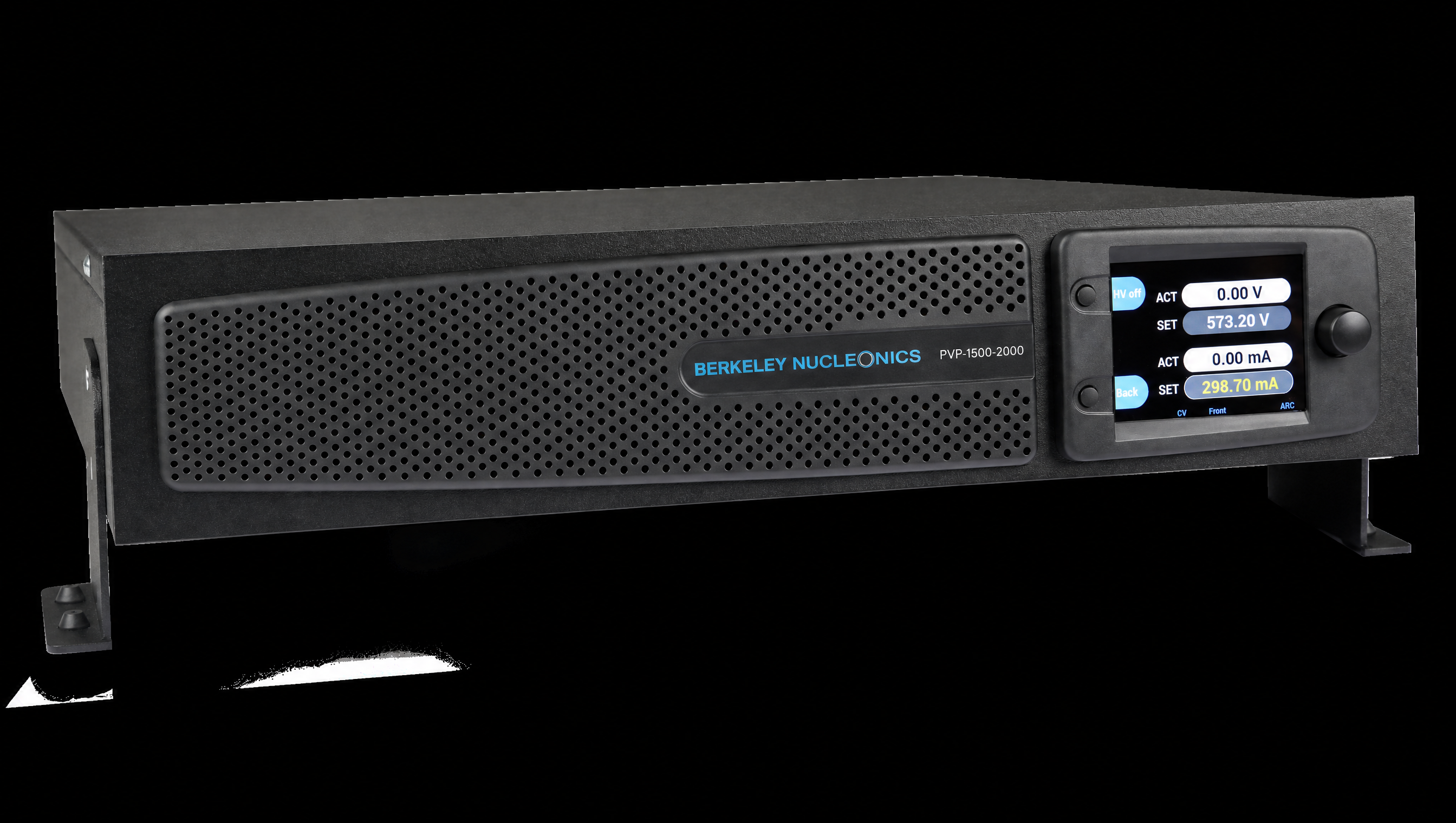
A DC supply is bounded by three numbers, and they are not independent. The PVP-Series spans 1.5 kV to 30 kV of output voltage across three power classes: 500 W, 2 kW, and 3 kW. Current capability follows from voltage and power. A 1.5 kV, 3 kW unit delivers up to 2000 mA, while a 30 kV, 500 W unit delivers up to 17 mA. The supply will hold whichever limit it reaches first.
This is the single most common selection mistake. Engineers pick a supply by its voltage headline, then discover that at their working voltage the available current is far lower than the peak number on the front of the datasheet. Always check the point where you actually plan to operate, not the corners of the rating. A unit that reaches 10 kV at 200 mA gives you 2 kW only at the top of its voltage range, and proportionally less current as you climb there.
| Power class | Example PVP-Series models | Voltage | Max current |
|---|---|---|---|
| 500 W | PVP-20000-25, PVP-30000-17 | 20 to 30 kV | 17 to 25 mA |
| 2 kW | PVP-1500-1400, PVP-5000-400, PVP-10000-200 | 1.5 to 10 kV | 200 to 1400 mA |
| 3 kW | PVP-1500-2000, PVP-5000-600, PVP-10000-300 | 1.5 to 10 kV | 300 to 2000 mA |
Model names encode the rating directly. PVP-5000-400 is a 5 kV, 400 mA unit. The polarity suffix follows: 1 positive, 9 negative, 5 reversible. Order references keep the original part numbers (for example, 00.210.143.x) so procurement maps one to one with the manufacturer.
3The Operating Envelope
The clearest way to see voltage, current, and power together is to plot them. A constant-power supply traces a hyperbola: as you raise voltage, the current ceiling falls so the product stays near the power class. Your load draws a line or a curve through that space, and the operating point sits where the two meet. If that point lands outside the envelope, the supply cannot serve the load, regardless of how impressive either headline number looks alone.
4Polarity
Polarity is a real decision, not a footnote. PVP-Series units come in three polarity styles. Positive and negative models reference one output terminal to earth and drive the other terminal above or below ground. Reversible models let you switch between positive and negative electrically, without rewiring, which suits a bench that serves several experiments or a test sequence that needs both polarities.
Separately, floating output models keep both terminals isolated from earth, so you can reference the output to a point in your own circuit. Floating outputs matter when the supply sits in series with another source, when you need to bias a stage that is not at ground, or when grounding the output would create a fault loop. The trade is that a floating output carries its own safety obligations, since neither terminal is automatically at a safe potential. We cover earth-referenced and floating outputs in depth in a companion note.
5Regulation and Ripple
Regulation describes how well the output holds its setpoint when something changes. Line regulation covers changes in the AC mains, and the PVP-Series holds tighter than +/-0.01% of nominal voltage across a +/-10% mains swing. Load regulation covers changes in the load current, and the PVP-Series holds within 0.05% of nominal voltage for a 10% to 90% load step. Response time back to within 0.1% is under 1 ms.
Ripple is the small residual AC riding on the DC output. The PVP-Series keeps voltage ripple at or below 0.01% of nominal voltage plus 100 mV. For a photomultiplier, an electron optic, or a precision deflection plate, that residual matters as much as the absolute setpoint, because it shows up directly as noise in the measurement. A supply that is accurate but noisy can still ruin a sensitive experiment. The numbers and what they mean for your result get a full treatment in the ripple and regulation note.
6Stability Over Time
A supply can hit its setpoint and still drift over a long run. The PVP-Series holds stability within 0.01% of nominal per 8 hours and a temperature coefficient at or below 0.01% of nominal per kelvin. For calibration and metrology work, where the supply is the reference rather than just the source, these are the numbers to read first. Full 16-bit setting resolution across roughly 0.01% to 100% of the nominal range lets you place the operating point precisely and repeat it.
7Interfaces and Automation
If the supply lives in an automated test rack, the control path is as important as the output. Every PVP-Series carries Ethernet and RS232 on board and speaks a SCPI command set, so it drops into a LabVIEW, Python, or instrument-control framework without a translation layer. The front panel offers a 3.5-inch color TFT with three-button navigation, structured menus, configurable code protection, and a time-tagged error and event log for traceability.
8Form Factor
The PVP-Series ships as a 19-inch rack-mount or benchtop unit with an integrated adapter, so the same hardware works in a rack or on a bench. Height is 2U, 3.5 inches (89 mm), and depth is 19.7 inches (500 mm). Weight starts near 28.7 lb (13.0 kg) for the lower-voltage units, around 36.4 lb (16.5 kg) at 20 kV, and about 38.6 lb (17.5 kg) at 30 kV. The AC inlet is an IEC 60320 C20 connector at the rear, fed from a wide-range single-phase mains with active power factor correction.
9Safety: Ramp and Arc
High voltage demands controlled behavior at both ends of a run and during faults. Two retrofittable options address this. Ramp control brings the output up and down on a defined gradient, from 1 V/s to 10 times the nominal voltage per second, so a sensitive load is never hit with a step. Arc detection watches for flashover, reports it, and can shut the output off, which protects both the supply and the device under test in breakdown-prone setups.
Beyond options, the PVP-Series discharges its output in under 60 seconds at no load (type dependent), which shortens the wait before a setup is safe to touch. Treat that figure as a minimum, not a guarantee, and always confirm zero potential with a meter before handling.
10From Use Case to PVP-Series Model
The matrix below is a starting point, not a substitute for a load analysis. Confirm the operating point, the polarity, and the accuracy target against the full specifications before you order.
| Use case | What it needs | Suggested PVP-Series starting point |
|---|---|---|
| Capacitor charging / pulsed power | High current at moderate voltage, fast recovery | PVP-1500-2000 (3 kW) |
| SiC / GaN double-pulse test | Stable bus, clean response, reversible if needed | PVP-1500-1400 or PVP-5000-400 |
| EV battery and powertrain HV test | Mid voltage, automation, repeatable setpoints | PVP-5000-600 (3 kW) |
| Calibration and metrology reference | Low ripple, tight stability, 16-bit setting | PVP-10000-200 or PVP-5000-400 |
| R&D / university HV lab | Flexible voltage, reversible polarity, SCPI | PVP-10000-300 (reversible) |
| Accelerator, magnet, or detector bias | High voltage, low current, fine control | PVP-20000-25 or PVP-30000-17 |
11Talk to an Engineer
The right supply is the one matched to your load, your accuracy target, and your safety plan, not the one with the largest number on the front. To work through an operating point, a polarity choice, or an automation path, contact Berkeley Nucleonics at 800-234-7858 or info@berkeleynucleonics.com.
For a quick question, chat with an engineer at berkeleynucleonics.com.