SPI programming and operation manual for the Berkeley Nucleonics Model 805-SG-1 signal source. It documents the SPI hardware interface and its communication specifications, plus the complete native command set used to control signal generator operation over SPI, with worked command examples.
Warranty. All Berkeley Nucleonics (BNC) instruments are warranted against defects in material and workmanship for a period of two years from the date of shipment. Berkeley Nucleonics will, at its option, repair or replace products that prove to be defective during the warranty period, provided they are returned to Berkeley Nucleonics and provided the preventative maintenance procedures are followed. Repairs necessitated by misuse of the product are not covered by this warranty. No other warranties are expressed or implied, including but not limited to implied warranties of merchantability and fitness for a particular purpose. Berkeley Nucleonics is not liable for consequential damages. The warranty on the internal rechargeable batteries (option B3) is one year from the date of shipment. Battery replacement is available through Berkeley Nucleonics and its distributors.
Important, please read carefully. Copyright. This manual is copyright by Berkeley Nucleonics and all rights are reserved. No portion of this document may be reproduced, copied, transmitted, transcribed, stored in a retrieval system, or translated in any form or by any means such as electronic, mechanical, magnetic, optical, chemical, manual or otherwise, without written permission of Berkeley Nucleonics.
1.Introduction
This manual provides information for remote operation of the Model 805-SG-1 using commands sent from an external controller via the SPI interface. It includes the following:
A general description of the SPI hardware interface and its communication specifications.
A complete listing and description of the native command set that can be used to control signal generator operation, with examples of command usage.
2.SPI Hardware Interface
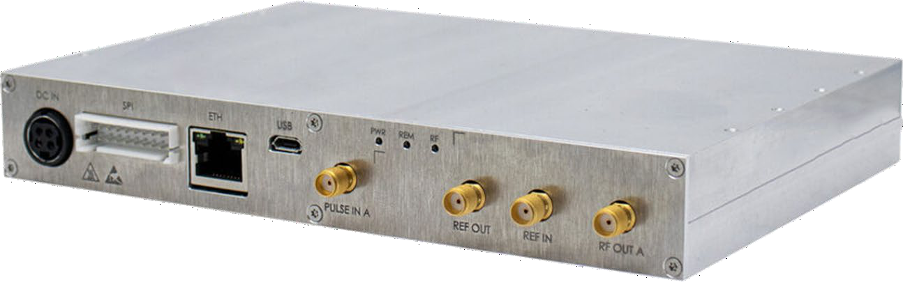
All instruments mentioned on the front page of this manual can be accessed through the SPI interface. This interface uses a native command set to pass commands to and read queries from the device.
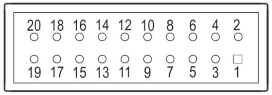
2.1 SPI Interface Connector
The SPI Hardware Interface consists of a standard SPI interface plus additionally assigned lines as defined below.
SPI clock. Supplied by the controlling host. The controlling host is the SPI master, the signal source device is the SPI slave.
SPI_SS#
13
Input
SPI Slave Select. This signal is an active low input from the host to the signal source device. It frames command communications. For each command, SPI_SS# goes low before the first bit is sent and goes high after the last bit is sent.
SPI_MISO
7
Output
Master In / Slave Out. Data line from the signal source device to the host.
SPI_MOSI
9
Input
Master Out / Slave In. Command / data line from the host to the signal source device.
TRIGGER
17
Input
Edge sensitive input. The trigger signal of +3.3 V can be configured for multiple trigger modes (see also the datasheet of the device).
LOCK
15
Output
Output indicates the RF output of the synthesizer is locked on its current setting (+3.3 V locked, 0 V unlocked).
REF_LOCK
16
Output
Output indicates the signal source device has detected an external reference signal and locked on that signal (+3.3 V locked, 0 V unlocked).
RESET#
18
Input
Internally pulled up to +3.3 V with 100 kΩ resistor. Active low signal, which has a minimum width of 1 ms, will reset the signal source device to a default state.
DC IN
3, 4
—
External power supply (see also the datasheet of the device). Redundant power supply input to the DC IN interface (supply with higher voltage will be chosen).
GND
8, 10, 19, 20
—
Ground.
DNC
1, 2, 5, 6, 12, 14
—
Do not connect. Reserved for factory / future use.
The SPI interface connector is a 20 pin, 2.50 mm spaced double-row header. BNC recommends HIROSE manufactured socket DF1B-20DS-2.5RC and corresponding contacts from its DF1B series.
2.2 SPI Signals and Timing
SPI timing. SPI timing graph and description will follow.
3.SPI Native Commands
Most of Berkeley Nucleonics signal source devices support an Ethernet or USB interface which communicates through SCPI commands with the host controller. However, the communication over the SPI interface of a device uses a specific native command set which is defined and described in this Programmer's Manual document.
The native command set consists of commands, parameters and return data on a binary definition (in some cases data can be ASCII interpreted, which is separately noted). A communication is always started with a command byte sent by the host. Command specific data is followed with a number of bytes as it is needed for the command and as it is specified and defined in this document in the specific command section.
There are two different types of commands which are further described below.
3.1 Control Commands
Control commands are used to control the device, like setting the RF output frequency or the RF output power. These commands are a one-way communication from host to device without return or acknowledge data.
A command starts with a 1-byte command code followed by the parameter data which is needed for the command. Therefore, the length of the sent data varies between the different commands.
3.2 Query Commands
Query commands are used to read data back from the device, like the current status of the device or the device ID. These commands always need to be executed twice. When sending the command for the first time, the host sends the command byte starting with a 1-byte command code followed by the number of bytes which need to be read back (data of these bytes does not care). In this time, the device is preparing the requested data to be read back. While sending the command for the second time, the return data of the device can be received by the host.
The number of bytes to read back differs between the different commands, therefore the length of the sent data varies between the commands.
4.SPI Native Commands Description — Control Commands
The table below summarizes the control commands, their command codes, parameters, units and default values.
Command
Command Code
Parameters
Unit
Default
Set Output Frequency
0x0C
<integer>
0.001 Hz
100 MHz
Set Output Power
0x03
<integer>
0.1 dBm
0 dBm
Blanking Mode
0x05
OFF | ON
—
OFF
Select Reference Source
0x06
INT | EXT
—
INT
Reference Output
0x08
OFF | ON
—
OFF
RF Output
0x0F
OFF | ON
—
OFF
Pulse Modulation
0x09
OFF | ON
—
OFF
ALC Enable
0x60
OFF | ON
—
ON
Power Search
0x67
—
—
—
SPI Disable
0x96
<integer>
ms
—
Set Output Frequency
Size (Bytes)
Header
Parameter
7
Code
Bits
Size (Bytes)
Bits
Value
0x0C
[55:48]
6
[47:0]
Frequency
This command sets the RF output frequency of the device.
Command Parameters
Parameters
Size (Bytes)
Bits
Value
Frequency
6
[47:0]
Frequency in 0.001 Hz
Default Values
Parameter
Default Value
Value (Hex)
Frequency
100 MHz
0x00174876E800
Set Output Power
Size (Bytes)
Header
Parameter
3
Code
Bits
Size (Bytes)
Bits
Value
0x03
[23:16]
2
[15:0]
Power
This command sets the RF output power of the device.
Command Parameters
Parameters
Size (Bytes)
Bits
Value
Power
2
[15:0]
Power in 0.1 dBm, negative values in two's complement
Default Values
Parameter
Default Value
Value (Hex)
Power
0 dBm
0x0000
Blanking Mode
Size (Bytes)
Header
Parameter
2
Code
Bits
Size (Bytes)
Bits
Value
0x05
[15:8]
1
[7:0]
Enable
This command enables (blanked) or disables (unblanked) RF output during frequency changes.
Command Parameters
Parameters
Size (Bytes)
Bits
Value
Enable
1
[7:0]
OFF (unblanked): 0x00 ON (blanked): 0x01
Default Values
Parameter
Default Value
Value (Hex)
Enable
OFF (unblanked)
0x00
Select Reference Source
Size (Bytes)
Header
Parameter
2
Code
Bits
Size (Bytes)
Bits
Value
0x06
[15:8]
1
[7:0]
Reference Source
This command selects internal or external source as reference signal. If external reference source is selected, external reference frequency is set to 10 MHz per default.
Command Parameters
Parameters
Size (Bytes)
Bits
Value
Reference Source
1
[7:0]
Internal Source: 0x00 External Source: 0x01
Default Values
Parameter
Default Value
Value (Hex)
Reference Source
Internal Source
0x00
Reference Output
Size (Bytes)
Header
Parameter
2
Code
Bits
Size (Bytes)
Bits
Value
0x08
[15:8]
1
[7:0]
Enable
This command enables (ON) or disables (OFF) the reference output port. If enabled, reference output frequency is set to 10 MHz per default.
Command Parameters
Parameters
Size (Bytes)
Bits
Value
Enable
1
[7:0]
OFF: 0x00 ON: 0x01
Default Values
Parameter
Default Value
Value (Hex)
Enable
OFF
0x00
RF Output
Size (Bytes)
Header
Parameter
2
Code
Bits
Size (Bytes)
Bits
Value
0x0F
[15:8]
1
[7:0]
Enable
This command enables (ON) or disables (OFF) RF output.
Command Parameters
Parameters
Size (Bytes)
Bits
Value
Enable
1
[7:0]
OFF: 0x00 ON: 0x01
Default Values
Parameter
Default Value
Value (Hex)
Enable
OFF
0x00
Pulse Modulation
Size (Bytes)
Header
Parameter
2
Code
Bits
Size (Bytes)
Bits
Value
0x09
[15:8]
1
[7:0]
Enable
This command enables (ON) or disables (OFF) pulse modulation, controlled by the external PULSE / TRIGGER port.
Command Parameters
Parameters
Size (Bytes)
Bits
Value
Enable
1
[7:0]
OFF: 0x00 ON: 0x01
Default Values
Parameter
Default Value
Value (Hex)
Enable
OFF
0x00
ALC Enable
Size (Bytes)
Header
Parameter
2
Code
Bits
Size (Bytes)
Bits
Value
0x60
[15:8]
1
[7:0]
Enable
This command enables (ON) or disables (OFF) RF output level control.
Command Parameters
Parameters
Size (Bytes)
Bits
Value
Enable
1
[7:0]
OFF: 0x00 ON: 0x01
Default Values
Parameter
Default Value
Value (Hex)
Enable
ON
0x01
Power Search
Size (Bytes)
Header
Parameter
1
Code
Bits
Size (Bytes)
Bits
Value
0x67
[7:0]
—
—
—
This command triggers a power search to optimize RF output level control.
SPI Disable
Size (Bytes)
Header
Parameter
3
Code
Bits
Size (Bytes)
Bits
Value
0x96
[23:16]
1
[15:0]
Off-time
This command disables the SPI interface of the device for a set amount of time.
Command Parameters
Parameters
Size (Bytes)
Bits
Value
Off-time
2
[15:0]
Off-time in ms
Examples
Set output frequency to 6.791 GHz
Convert frequency to mHz: 6'791'000'000'000 mHz
Convert frequency in mHz to 48-bit hexadecimal: 06 2D 27 24 86 00
Append command header in front of the frequency: 0C 06 2D 27 24 86 00
Send command: 0C 06 2D 27 24 86 00
Set output power to -10 dBm
Convert power to dBm/10: -100 dBm/10
Convert power in dBm/10 to 16-bit hexadecimal: FF 9C
Append command header in front of the power: 03 FF 9C
Send command: 03 FF 9C
Enable RF output
Set parameter byte to enable RF output: 01
Append command header in front of the parameter: 0F 01
The table below summarizes the query commands, their command codes, return data and units.
Command
Command Code
Return Data
Unit
Get ID
0x01
Model# | Option# | SW Version | Device#
—
Get Device Status
0x02
Ext Ref | RF Lock | Ref Lock | RF Out | Ref Out | Blanking
—
Get Output Frequency
0x04
<integer>
0.001 Hz
Get Output Power
0x0D
<integer>
0.1 dBm
Get ID
Command
Return Data
Size (Bytes)
Code
Bits
Size (Bytes)
Bits
Value
12
0x01
[95:88]
12
[87:0]
Model# | Option | SW Version | Device#
This command returns the identification data of the device, including model number, options, software version and device number.
Command Parameters
Parameters
Size (Bytes)
Bits
Value
Don't care
11
[87:0]
—
Return Data
Parameters
Size (Bytes)
Bits
Value
Don't care
1
[95:88]
—
Model#
2
[87:72]
Two digit ASCII model number (link to SN?)
Option
2
[71:56]
Two digit ASCII options indicator (link to SN?)
SW Version
2
[55:40]
Binary software version number
Device#
5
[39:0]
Five digit ASCII device number (link to SN?)
Get Device Status
Command
Return Data
Size (Bytes)
Code
Bits
Size (Bytes)
Bits
Value
2
0x02
[15:8]
2
[7:0]
Ext Ref | RF Lock | Ref Lock | RF Out | Ref Out | Blanking
This command returns the status bits of the device, including external reference status, RF and reference lock status, RF and reference output status and blanking status.
Command Parameters
Parameters
Size (Bytes)
Bits
Value
Don't care
2
[15:8]
—
Return Data
Parameters
Size (Bytes)
Bits
Value
Don't care
1
[15:8]
—
Ext Ref
1
[0]
Internal Reference (0); External Reference (1)
RF Lock
[1]
RF locked (0), RF unlocked (1)
Ref Lock
[2]
Reference locked (0), reference unlocked (1)
RF Out
[3]
RF output disabled (0), RF output enabled (1)
—
[4]
0
Ref Out
[5]
Ref output disabled (0), ref output enabled (1)
Blanking
[6]
Blanking disabled (0), blanking enabled (1)
—
1
[7]
0
Get Output Frequency
Command
Return Data
Size (Bytes)
Code
Bits
Size (Bytes)
Bits
Value
7
0x04
[55:48]
7
[47:0]
Frequency
This command reads the current RF output frequency of the device.
Command Parameters
Parameters
Size (Bytes)
Bits
Value
Don't care
6
[47:0]
—
Return Data
Parameters
Size (Bytes)
Bits
Value
Don't care
1
[55:48]
—
Frequency
6
[47:0]
Frequency in 0.001 Hz
Get Output Power
Command
Return Data
Size (Bytes)
Code
Bits
Size (Bytes)
Bits
Value
3
0x0D
[23:16]
3
[15:0]
Power
This command reads the current RF output power of the device.
Command Parameters
Parameters
Size (Bytes)
Bits
Value
Don't care
2
[15:0]
—
Return Data
Parameters
Size (Bytes)
Bits
Value
Don't care
1
[23:16]
—
Power
2
[15:0]
Power in 0.1 dBm, negative values in two's complement
Examples
Get output frequency
Send command: 04 00 00 00 00 00 00
Send command: 04 00 00 00 00 00 00
Read return data: 00 06 2D 27 24 86 00
Disregard "Don't Care" bits from received data: 06 2D 27 24 86 00
Convert data to mHz: 6'791'000'000'000 mHz
Convert data to Hz: 6.791 GHz
Get device status
Send command: 02 00
Send command: 02 00
Read return data: 00 2E
Disregard "Don't Care" bits from received data: 2E
Interpret status bits:
Bit 0: 1 → External reference
Bit 1: 0 → RF locked
Bit 2: 0 → Reference locked
Bit 3: 1 → RF output enabled
Bit 5: 1 → Reference output enabled
Bit 6: 0 → Blanking off
6.Document History
Version
Date
Author
Notes
0.1
05.10.2023
DD
First draft
7.Contact Us
Berkeley Nucleonics Corporation
2955 Kerner Blvd.
San Rafael, CA 94901