1General Information
The MOD745 device provides four high precision independent delay channels. Access to these four outputs (T1 to T4) is given by four BNC connectors on the front panel. The achieved delay resolution is about 0.25 ps, and trigger-to-channel jitter is less than 25 ps (Annex B). T1 to T4 can deliver up to 5 V, 2 ns rise time max (Annex A), into 50 Ω. Amplitude and width are adjustable on each output channel, either programmed from the front panel or via Ethernet.
A T0 output pulse is also available. It gives a time reference for each generated delayed output. This high accuracy and precision device is suitable for systems and experiments in science or industry that require a reliable timing solution.
The MOD745 also provides four optional delay channels at front panel T5 to T8, with a delay resolution of 1.25 ns, trigger-to-channel jitter less than 50 ps, and a common 2 to 5 V tunable amplitude. The internal timebase reference is a TCXO with a stability of 0.5 ppm. An optional OCXO with 50 ppb precision can replace the standard one.
The device offers three operating trigger modes: repetitive (internal or external source), single shot (internal, external or asynchronous source), and a burst mode (internal, external or asynchronous source). A web page accessed via the Ethernet link provides a simple method to configure the settings for each channel, amplitude, width, trigger source, and trigger mode, and to control operation. You can save and recall settings.
Instrument Options
| Option | Description |
|---|---|
| 745-4C | Standard device |
| 745-8C | Extension to 8 channels (4 optional channels with 1.25 ns resolution) |
| C | Clock output |
| G | Gate input |
| O | OCXO 50 ppb |
| USB | Serial communication via USB port |
Package Contents
The box you receive should contain the following:
- MOD745 Digital Delay Generator
- PDF user manual and LabVIEW VIs, available for download from the manufacturer support portal
- Certificate of calibration
For more information about BNC products, see our web site: www.berkeleynucleonics.com.
What You Need to Get Started
To set up and use the MOD745, you need the following items:
- MOD745 Digital Delay Generator
- MOD745 user manual
Unpacking Caution
Operating Temperature
The MOD745 can be operated where the ambient air temperature is 10°C to 35°C, and can be stored in ambient temperature from -10°C to +60°C. The MOD745 is cooled by air circulation.
Self-test
The unit model, firmware version, serial numbers, and the result of the self-test procedure are displayed one minute after power on. After 30 seconds, if the test is good, then "self-test" disappears and the device can be used. If the test is not OK, then "self-test" stays displayed and the device is locked.
The Device Software
LabVIEW VIs are provided with the MOD745 device. They allow users to control or configure the equipment as planned. These VIs can be integrated into a top-level VI where several devices are controlled. The communication is done with an Ethernet connection.
Power Fuses
The MOD745 is protected against short circuit by means of one fuse according to the nameplate of the power supply (F2.5H250V).
RAM with Battery Backup
The MOD745 has a RAM with battery backup in which settings of the instrument can be stored (Lithium battery ref 2032).
2Specifications
Delays
| Parameter | Value |
|---|---|
| Channels | 4 independent delay outputs |
| Range | 0 to 20 seconds |
| Resolution | 0.25 ps |
| Jitter | 25 ps RMS + delay × 10-7 (external trigger to any output, Annex); 20 ps RMS + delay × 10-7 (channel to channel, Annex); < 5 ps RMS for short delay (channel to channel) |
| Accuracy | < 250 ps + delay × 10-7 |
| Time base | 0.05 ppm stability |
Trigger Source
| Parameter | Value |
|---|---|
| Internal | 2 timers tunable in Hz or ns; 1 Hz to 1 MHz, 1 Hz resolution; 1 µs to 4 s, 5 ns resolution |
| External | Repetition rate < 1 MHz; prescaler 1 to 216-1 |
Clock Input
| Parameter | Value |
|---|---|
| Frequency | 10 or 80 MHz, 50% duty cycle. Ask factory for custom clock frequency. |
User Memory
Up to 4 sets of MOD745 parameters can be stored and recalled via the front panel or Telnet.
General Specifications
| Parameter | Value |
|---|---|
| Size | 215 x 245 x 135 mm |
| Power | 50 W, 110 to 240 V |
| LEDs | Orange: trigger on |
| Software | Control panel web page from embedded web server for IE, Firefox, or Chrome |
Output T1 to T4 (A to D), BNC Connector
| Parameter | Value |
|---|---|
| Amplitude | 2 to 5 V, 0.1 V resolution |
| Width | 100 ns to 10 µs, 5 ns resolution |
| Load | 50 Ω |
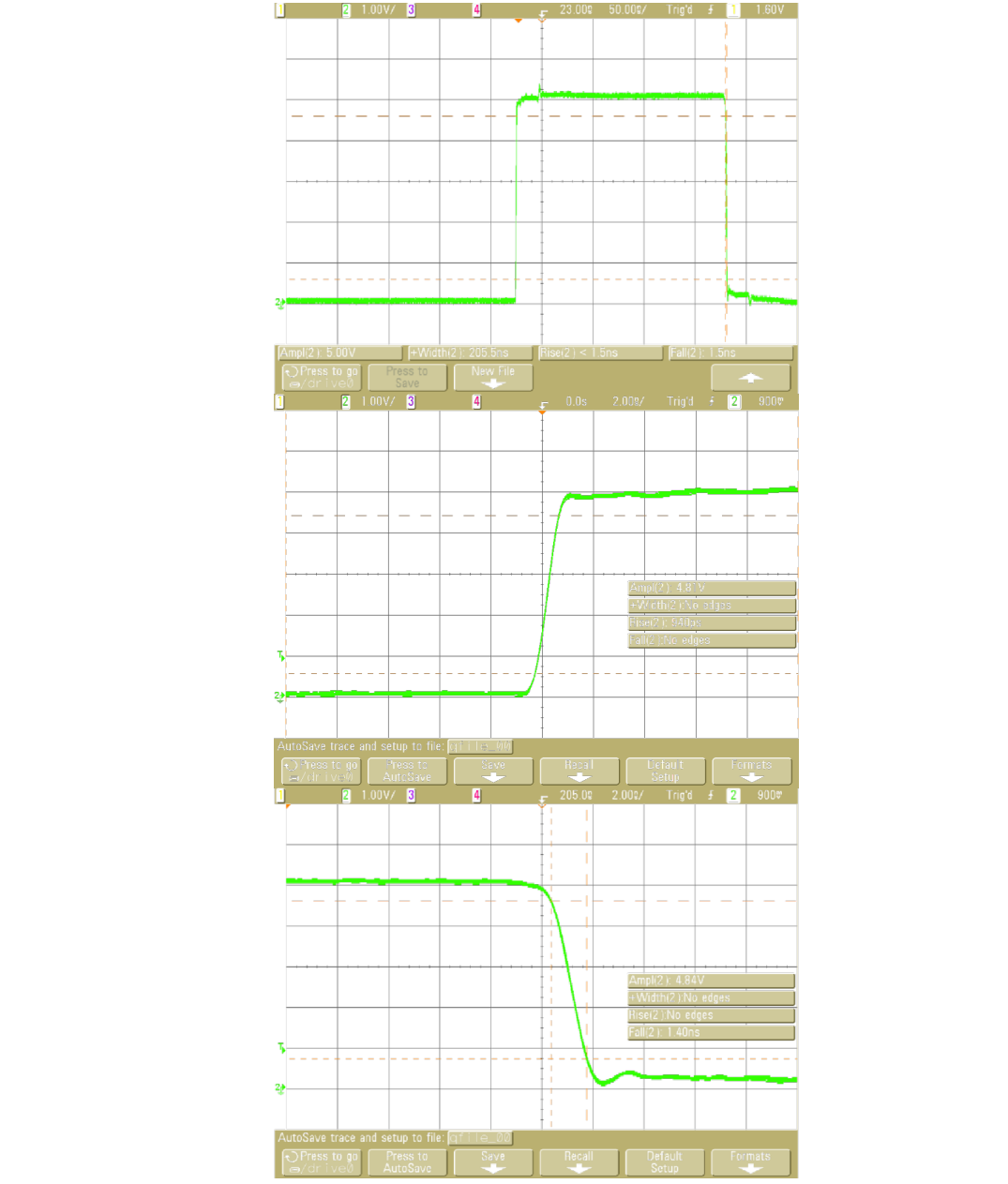
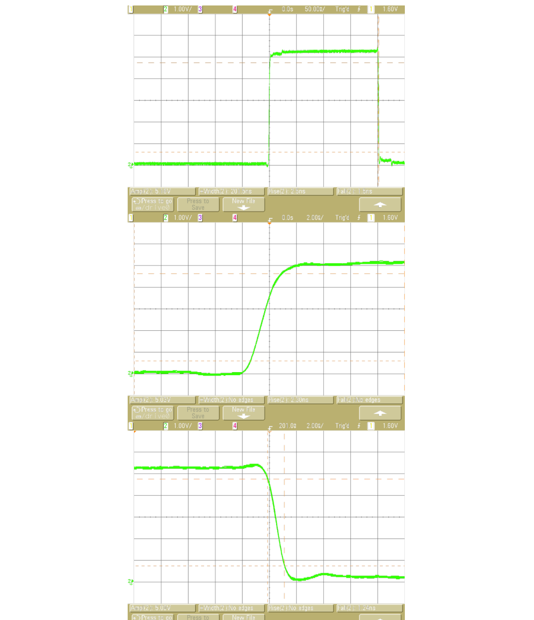
| Rise time | < 2 ns max, 900 ps typical |
| Fall time | < 5 ns max, 2 ns typical |
Options
745-8C: 4-auxiliary delay output extension. Output T5 to T8 (E to H):
| Parameter | Value |
|---|---|
| Channels | 4 independent delay outputs |
| Range | 0 to 20 seconds |
| Resolution | 1.25 ns |
| Jitter | 50 ps RMS + delay × 10-7 (external trigger to any output) |
| Accuracy | < 1 ns + delay × 10-7 |
| Amplitude | 2 to 5 V |
| Width | 100 ns to 10 ms, 5 ns resolution |
| Load | 50 Ω |
| Rise and fall time | < 5 ns |
| Connector | BNC on front panel |
Trigger Mode
- Trigger level, from 0.1 to 5 V; internal load 50 Ω
- Positive or negative slope
- Minimum trigger delay < 60 ns
- Single, repetitive, or burst
Burst Specifications
- Pulse number: 2 to 216-1
- Period: 1000 ns to 1 s
Gate Mode
- 2 settings: General or Individual
- Gate source: active high, repetition rate < 100 kHz
Additional Options
- -C: Clock output (10 MHz, +/- 1 V, square)
- -G: Gate input
- -O: OCXO 50 ppb
- -USB: Serial communication via USB port
3Front Panel Overview
The Model 745 front panel is composed of several kinds of elements: the user interface, which consists of a keyboard and an LCD display that allows the user to program various settings and to interact with the device in local mode; 4 status LEDs; and BNC connectors.
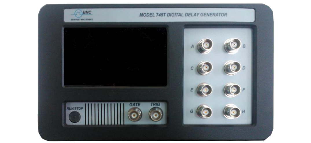
LCD Screen
The screen is a 4.3" touch screen.
RUN/STOP Button
Global RUN/STOP. It enables the user to RUN or STOP all output channels.
BNCs
One input Trigger, one Gate input, and 4 independent output channels (A to D) are available. The output voltage is tunable from 2 to 5 V for each output independently, and each one has to be terminated in 50 Ω. The input Trigger BNC connector provides a trigger signal operating up to 50 kHz.
Optional BNC
The four optional outputs (E to H) connectors are 50 Ω impedance with adjustable amplitude, delay, and width.
4Rear Panel Overview
All optional output connectors and modules appear on that side of the device. The other features are listed below.
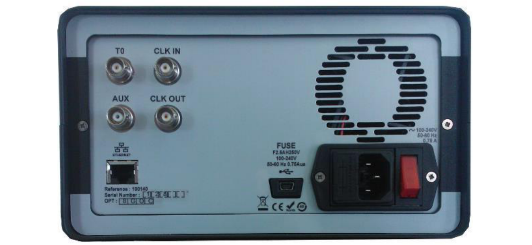
Power Switch
The unit is turned on by depressing the Power button. The MOD745 can be operated from 100 to 240 V at a line frequency of 50 to 60 Hz.
T0 Output
A reference pulse output is available. It delivers a fixed amplitude pulse with adjustable width. Terminated in 50 Ω.
Optional BNCs
Clock input and clock output connectors are available. The CLK IN connector accepts either a 10 MHz or 80 MHz (or custom) clock frequency. The optional clock output (CLK OUT) comes from the CLK IN connector or from the internal oscillator, if the clock in signal is not present. For now, the AUX connector is not used.
Ethernet Port
A RJ45 Ethernet connector is available to control the Model 745 with a computer. See Section 8.
USB Port (Option)
A female USB connector can be available, allowing serial communication with the MOD745. See Section 8, Programming, for command syntax.
5Menu Structure (Navigating the MOD745)
A three level menu is available:
- A main menu to display settings
- Sub-menus to select the parameter to set
- Keyboard to set the new parameter value
The following is a presentation of the display menu for an 8-channel unit. From the main menu (Figure 3), the user can access every MOD745 setting by pressing the selected parameter zone.
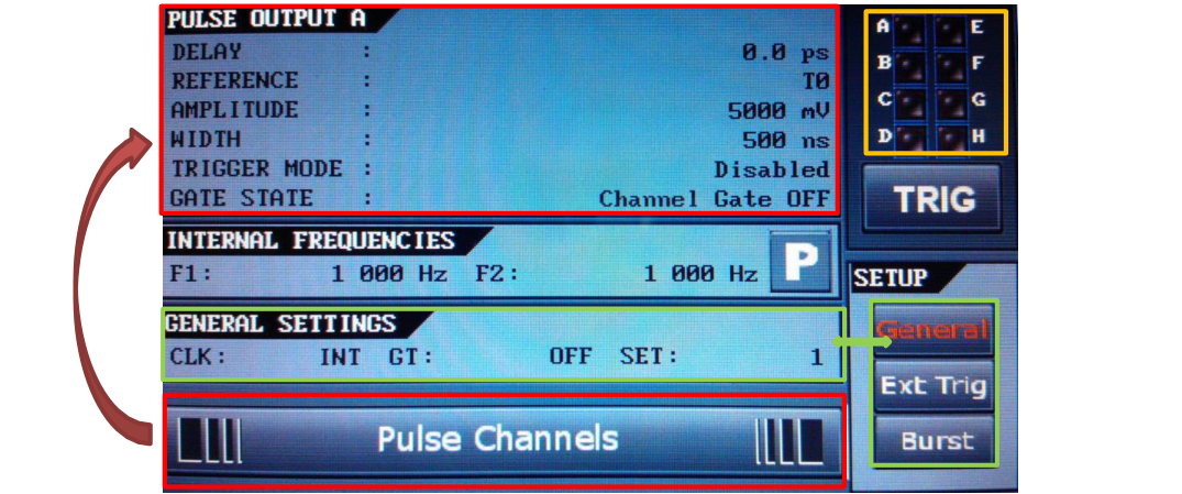
Main Display
| Settings name | Description | Special |
|---|---|---|
| Pulse Output | Channel settings: trigger, amplitude, width, delay, reference, gate | Use the Pulse Channels bar to change the displayed channel |
| Internal Frequencies | Frequency or period settings of internal trigger generators 1 and 2 | Press the P button to display period settings |
| General | Clock, gate, store/recall, and network settings | Press General in the Setup box to display the menu |
| External trigger | Trigger settings: threshold, slope, and prescaler | Press Ext Trig in the Setup box to display the menu |
| Burst | Input clock setting: 10 or 80 MHz | Press Burst in the Setup box to display the menu |
| Trigger | Manual trigger button | |
| Channel status | Display the current channel status | Press the zone to clear channel status |
Channel Settings
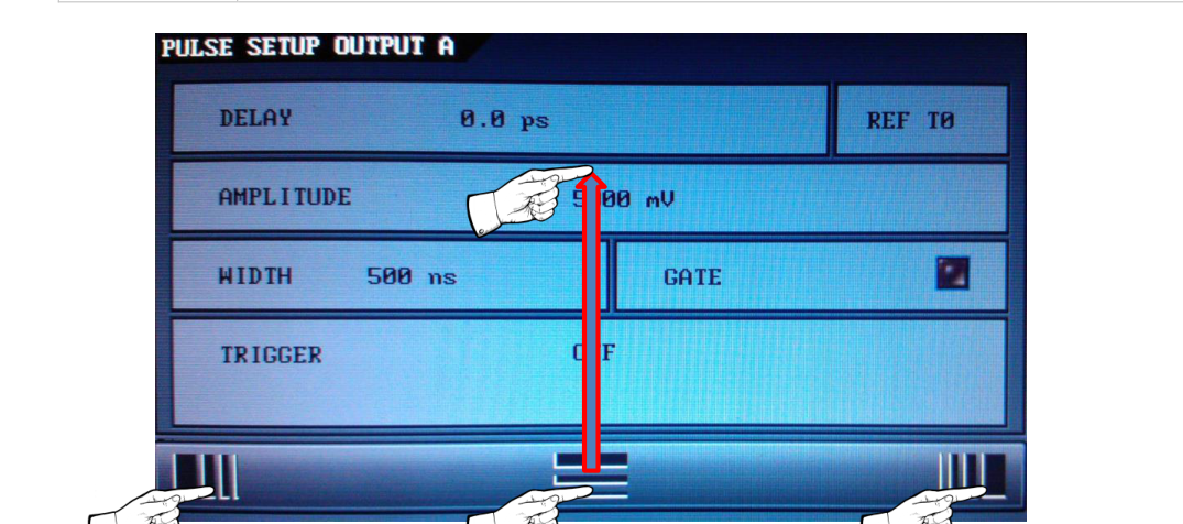
| Displayed name | Description and settings |
|---|---|
| TX TRIG= | To select trigger source. OFF: trigger signal is inhibited. IN1: trigger signal coming from internal frequency 1. IN2: trigger signal coming from internal frequency 2. EXT: trigger signal coming from the front panel (TRIG IN). SS1: single shot trigger synchronous with internal frequency 1. SS2: single shot trigger synchronous with internal frequency 2. SSE: single shot trigger synchronous with trigger input. LSS: software single shot trigger. BST: pulse train trigger synchronous with internal frequency or trigger input. |
| TX RET= | To select the channel delay reference: T0 and A to H |
| TX Delay= | To adjust output pulse delay of channel (A to D, 1 ps resolution display; E to H, 1.25 ns resolution display) |
| TX Ampl= | To adjust output pulse amplitude of channel A to H |
| TX Width= | To adjust output pulse width of channel TX |
| TX Gate | To set channel gate mode On or Off (available if general gate mode is set to "Channel Gate") of channel A to H |
| RETURN MENU | To return to main menu |
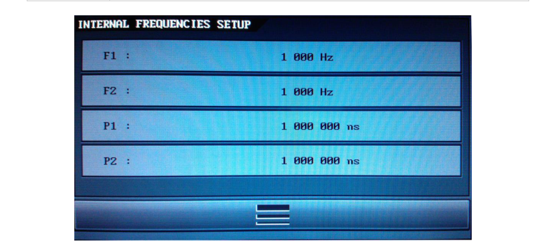
Internal Frequency Display
| Displayed name | Description and settings |
|---|---|
| Frequency 1 | Frequency of internal trigger generator 1 |
| Frequency 2 | Frequency of internal trigger generator 2 |
| Period 1 | Period of internal trigger generator 1 |
| Period 2 | Period of internal trigger generator 2 |
| RETURN MENU | To return to main menu |
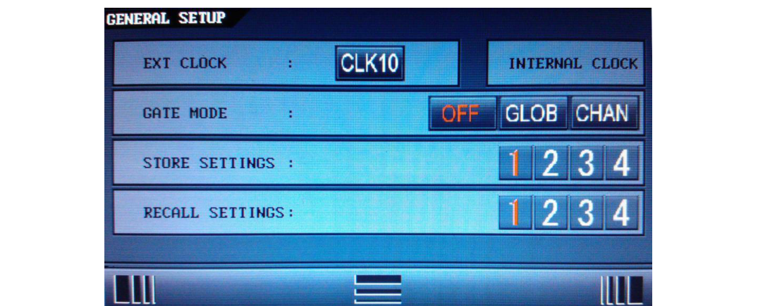
General Settings
| Displayed name | Description and settings |
|---|---|
| Ext Clock | Input clock setting: 10 or 80 MHz |
| Gate Mode | To select the gate mode. General gate: to aim every output. Channel gate: to set individual behavior for each channel (independent gate modes set in each Tx sub-menu). |
| Store x | To store current MOD745 configuration in conf x (x = 1 to 4) |
| Recall x | To recall conf x MOD745 configuration |
| RETURN MENU | To return to main menu |
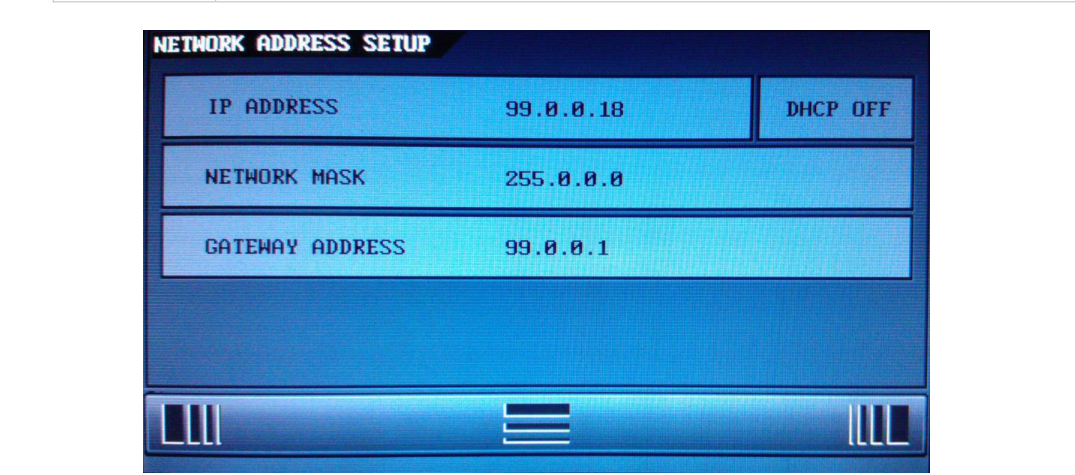
| Displayed name | Description and settings |
|---|---|
| IP ADDRESS | Set the instrument's IP address |
| NET MASK | Set the instrument's IP mask |
| GATEWAY ADDRESS | Set the instrument's IP gateway |
| USE DHCP | YES (automatic IP address assignment) or NO (for manual IP assignment) |
| LANGUAGE | Select French or English language for menu |
| RETURN MENU | To return to main menu |
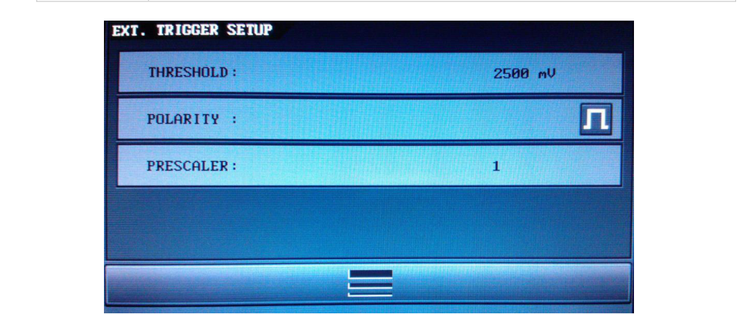
External Trigger Settings
| Displayed name | Description and settings |
|---|---|
| Polarity | To trigger on rising edge or on falling edge value of the Trig Ext input |
| Threshold | To adjust the threshold value of the Trig Ext input |
| Prescaler | To prescale the Trig Ext input frequency by a factor N (N = 1 to 216-1) |
| RETURN MENU | To return to main menu |
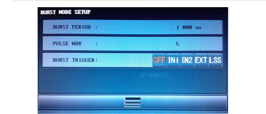
Burst Mode Settings
| Displayed name | Description and settings |
|---|---|
| Burst Trigger | To select the trigger source: Int, Ext, or manual |
| Pulse Number | To select the pulse number in each burst to generate (from 2 to 216-1) |
| Pulse Period | To select the period between burst pulses (from 1000 ns to 1 s) |
| RETURN MENU | To return to main menu |
6Operating Information
Operating Principles
The principle of the programmable delay generator is described in the figure below.
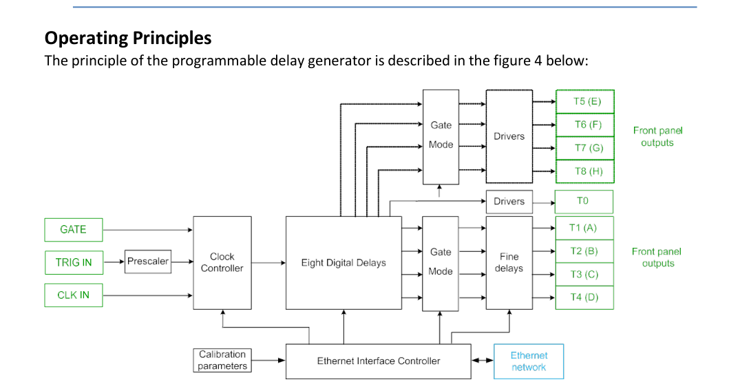
The trigger source can be provided by the TRIG IN input, by an internal trigger, or by a software command trigger. Repetitive, single shot trigger, and burst modes are available with internal and external sources. An asynchronous single shot and burst mode are also available.
Repetitive Triggers
When the external trigger source is selected, a rising edge on TRIG IN starts a delay sequence. The sequence is depicted in Figure 12. A prescaler value can be used to divide the Trig Ext input signal frequency. To get this feature, the user has to select EXT as the trigger source on the device via the front panel or via remote control (web page, Ethernet link).
If the internal trigger source is selected, the user can specify the needed trigger source via the front panel or via remote control. Two frequency generators derived from the input clock can be used as repetitive triggers: IN1 and IN2, corresponding to programmable Frequency 1 and 2. The use of the internal trigger is depicted in Figure 14. Frequency generation restarts when a push on the ESC button is detected while the Frequency/Period menu is displayed.
Single Shot Triggers
Three single shot modes are available: one synchronous to the external source (SSE), one to an internal source (SS1 synchronous to Frequency 1, SS2 synchronous to Frequency 2), and the last an asynchronous one (LSS). Each single shot mode is triggered by a software command. The software trigger command is available either via remote control or via the front panel. Single shots synchronous to an external source are depicted in Figure 12. The same principle can be applied to any of the internal sources.
Burst Mode
The Burst mode is defined by its trigger source (internal, external, software/single shot, or repetitive), its pulse number in each burst, and the period between pulses. A pulse train can be independently set and defined on each channel: amplitude, width, and delay are defined in the corresponding channel menu. An example of Burst mode is depicted in Figure 15. To generate a burst on a specified channel, first the user has to configure the Burst mode itself (trigger, pulse number, and pulse period), and then select "Burst (BST)" in the trigger source selection of the concerned channel.
Output Channels
A T0 output pulse is the time reference of the delay output. It is generated for each selected trigger. Each output delayed pulse value, T1 to T4, can be independently tuned in level, absolute or relative delay, and width. All values (delay, delay reference, level, width, gate) are saved in memory except the trigger source. Each output delayed pulse value, T5 to T8, can be independently tuned in absolute or relative delay and width. All values (delay, delay reference, width) are saved in memory except the trigger source. Calibration parameters are saved onboard. After power on, all trigger sources are off. Note that several output channels can only be triggered by the same source, that is to say an internal OR external source.
Gate Mode
Each channel can be independently or simultaneously gated by the Gate In input signal. A Gate menu is available in the main menu of the MOD745 device and in each Tx sub-menu. Two different modes can be selected in the general Gate menu:
- A GENERAL mode to gate simultaneously all channels.
- A CHANNEL mode to gate independently each channel by setting in each Tx sub-menu the desired gate state ("1" active, "0" inactive).
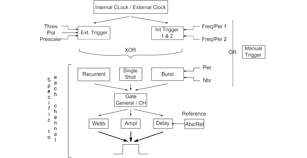
Configuration Summary
Figure 11 presents a functional diagram of the device. The different operation modes are illustrated.
Timing Principle Using External Trigger
When the device is in a rest state (no current output signals), a rising edge on a trigger starts a delay sequence. The trigger comes from TRIG IN or from a software command trigger (depending on the selected channel source). The sequence includes two external trigger phases:
- After an insertion delay (< 60 ns), a pulse appears on each channel after a specified delay.
- At the end of the sequence, after the last delayed pulse, the delay generator is ready for repetitive trigger mode.
When a sequence is in progress, the instrument does not respond to a trigger event. The MOD745 must be configured (trigger, delay, etc.) before starting any sequences.
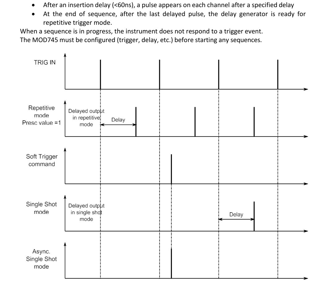
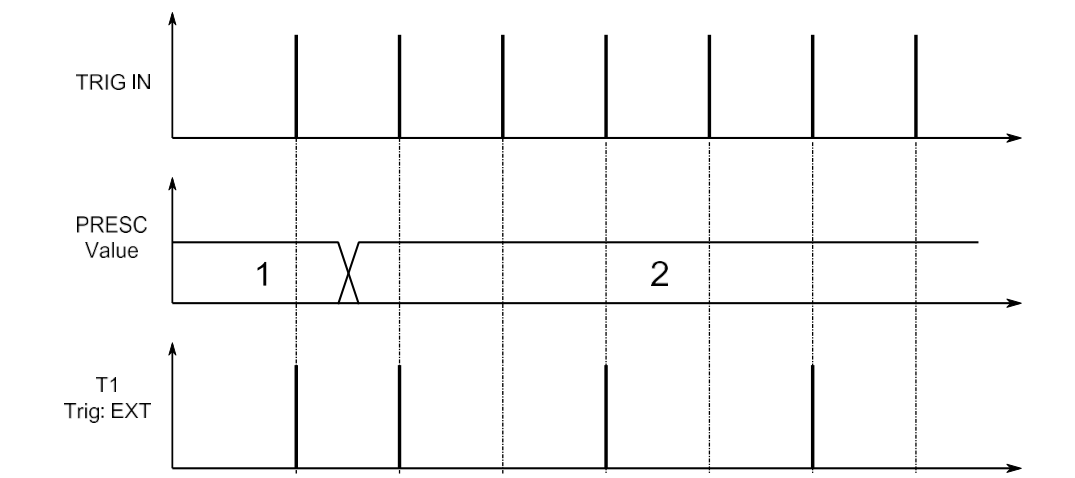
In response to an input pulse, the device can generate a single delayed output (single shot) or repetitive delayed output (repetitive mode with a Trig In prescaler value = 1). As explained before, the single shot pulse is conditioned by the soft trigger command. The use of the prescaler value is depicted in Figure 13. The T1 channel trigger source is set to external trigger.
Timing Principle Using Internal Trigger
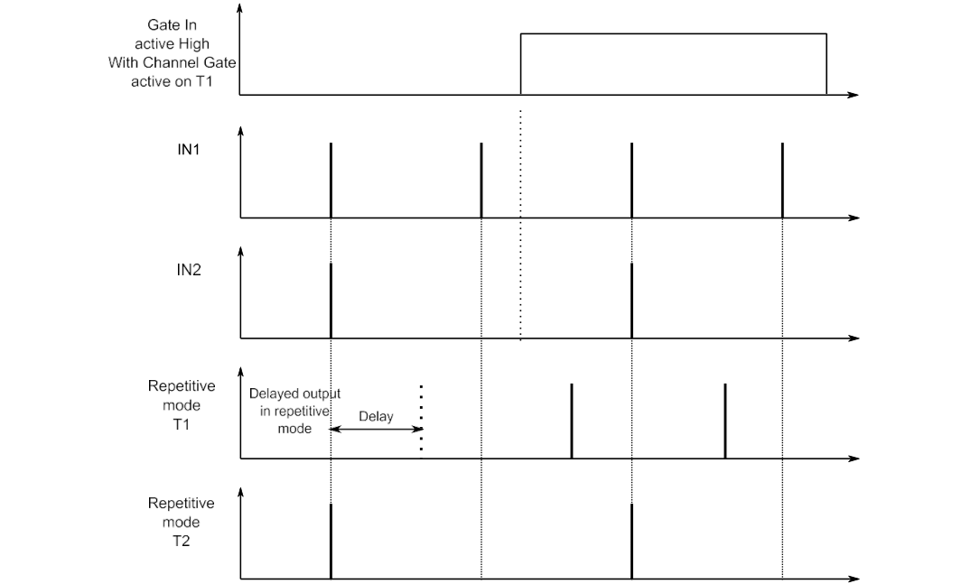
In internal trigger mode, two tunable frequencies are available (IN1 and IN2). In Figure 14, the T1 output uses the IN1 trigger with a specified delay of 0 ps, and the T2 output uses the IN2 trigger with a non-null delay. The MOD745 must be configured (trigger, delay, etc.) before starting any sequences. The individual Channel Gate Mode is also depicted in Figure 14. It is obtained by setting general Gate Mode to "CHANNEL" and T1 Gate mode to "ON". The result is that the Gate In signal allows the pulse output of the channel T1.
The width parameter does not appear in Figures 12 and 14. Note that the frequency f used as the repetitive input trigger (internal or external) and the maximum width of a corresponding output channel TX are linked by:
Max Width TX = 1 / (4f)
Timing Principle Using Burst Mode
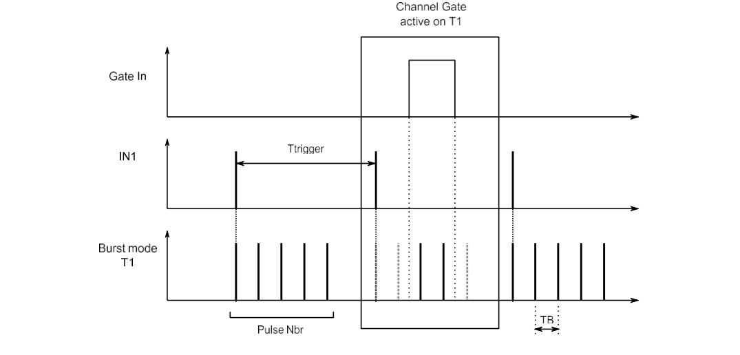
Each channel can be independently set to Burst mode. In the following example, the Burst trigger has been set to IN1, the Burst pulse number to 5, and the Burst period to TB.
The minimal burst period value is 1000 ns. Note that this value depends on the Burst trigger period value and on the Burst pulse number:
TB min = T trigger min / Pulse Nbr
So, to get a TB min = 1000 ns, we can configure the device as follows:
- Pulse nbr max = 5
- T trigger min = 5000 ns
As depicted in Figure 15, in the case of a generation of a pulse train (Burst Mode) on a channel, the Gate In signal can allow some pulses among the pulse train. Note that when a delay D is specified on a channel using Burst mode as the trigger mode, the MOD745 manages the delay generation according to that rule:
- If delay D > TB - 15 ns, the delay generation is shared between the delay register specific to the channel (Dchan = TB - 15 ns) and the delay register associated to the burst trigger generation (DBST = D - TB + 15 ns).
- If delay D ≤ TB - 15 ns, the delay generation is managed as usual, that is to say by using the selected channel delay register.
To summarize: D = Dchan + DBST when D > TB - 15 ns. When several channels are using Burst mode as the trigger mode and one of the specified delays leads to the DBST register use (D > TB - 15 ns), the DBST value will be ignored (each channel will be delayed by DBST).
7Operating Example
Default Values
These values are stored by default:
| Parameter | Default value |
|---|---|
| IP | 99.0.0.18 |
| Gateway | 99.0.0.01 |
| NetMask | 255.0.0.0 |
| Frequency 1 | 1000 Hz |
| Frequency 2 | 1000 Hz |
| TX Level | 5 V |
| TX Width | 200 ns |
Initial Setup
Turn on the Model 745 with the rear panel power switch. After 30 seconds, the following information is displayed:
MOD745 · Sn xxxxx,4 V1 · SELF TEST
Setting Up the Instrument (Recurrent Mode)
The aim is to set a repetitive frequency of 1000 Hz to output pulse T1 (A), with an amplitude of 4 V and a width of 1 µs. Use the touch screen to configure the settings as follows:
- Go to the internal frequency display.
- Set Freq 1 to 1000 Hz and return to the main menu.
- Go to the channel setting display and select channel T1 (or A).
- Set amplitude to 4 V and width to 1 µs.
- Select IN1 as the trigger source.
As soon as T1 (A) is set to IN1, the main display LED of T1 (A) will be on, indicating that there is an output signal on the T1 (A) connector. With an oscilloscope you can check the channel T1 (A). The measurement should be a rectangular shape with repetitive frequency = 1000 Hz, amplitude = 4.0 V, width = 1.0 µs.
Setting Up the Instrument (Single Shot Mode)
The procedure explained before can be followed up to the trigger choice. Three single shot modes can be set (external: SSEXT; internal: SS1 and SS2; asynchronous: LSS). Once the single shot trigger mode is set, the user has to send a software command to trigger the single shot output pulse. To send this software command, three ways are available:
- Via the front panel: in the general menu, by pressing the TRIG button.
- Via a Telnet command, by sending the RUN command to the device.
- Via the web page, by pressing the manual trigger button in the Trigger menu.
Setting Up the Instrument (Burst Mode)
The aim is to set channel T1 (A) in Burst mode to get:
- A 5 V, 200 ns width, 0 ns delay pulse
- 100 Hz IN1 trigger source
- Burst period 100000 ns, pulse number = 10
First the user has to configure the F1 frequency to 100 Hz and then the Burst Mode itself. That is to say, set in the Burst Mode menu:
- Burst Trigger: IN1
- Burst Period: 100000
- Burst pulse number: 10
Once this has been done, the user has to set the width, delay, and trigger source (BURST) in the T1 channel sub-menu. The device will start to generate the requested pulse train.
Stop the Generator
To stop the generation of that repetitive pulse, you have to set the T1 trigger to the OFF value. This will switch off the corresponding LED. With an oscilloscope you can check if the output signal is switched off.
8Programming
Serial Communication (USB Port)
To access the MOD745 via the USB port, you have to configure the connection as follows:
| Parameter | Value |
|---|---|
| Baud rate | 38400 |
| Data bits | 8 |
| Stop bit | 1 |
| Parity | None |
| Flow control | None |
Ethernet Connection and Communication
For connection over a LAN, you have to do the following:
- Connect the instrument to the LAN physically.
- In the graphical user interface, specify the LAN address.
- On the control PC, enter the instrument's IP address.
After the connection has been established, the following commands can be used to modify the settings:
- Set the instrument's IP address with:
IP XXX.XXX.XXX.XXX - Query the instrument's IP address with:
IP?returns:IP XXX.XXX.XXX.XXX - Set the instrument's IP mask with:
NM XXX.XXX.XXX.XXX - Query the instrument's IP mask with:
NM?returns:NM XXX.XXX.XXX.XXX - Set the instrument's IP gateway:
GW XXX.XXX.XXX.XXX - Query the instrument's IP gateway with:
GW?returns:GW XXX.XXX.XXX.XXX
About Telnet Ports
Three ports can be used to configure the communication link and/or the microcontroller used to communicate:
| Port | Use |
|---|---|
| 4000 | General communication port |
| 4001 | Re-initialization communication port. Used to reinitialize the communication between the microcontroller and PC. Used in case of a frozen device. |
| 4002 | Force reset the microcontroller. Used in case of a frozen device. |
Command Structure (Ethernet and USB Connection)
Each command description is composed of at least some of the following items (all commands are used in a Telnet prompt): full command syntax, form (Set / Query), brief description, parameters, RST value, specified limits, and example.
*IDN?
| Syntax | *IDN? |
| Form | Query |
| Description | Queries instrument identification. Answer gives instrument model, serial number, and firmware version. |
| Example | BNC,MODEL 745,53901/F,V1.1 means instrument model MOD745; serial number 53901; channel number F means 4 active channels (FF means 8 active channels); software version 1.1 |
BURST TRIG
| Syntax | BTRIG Source / BTRIG? source |
| Form | Set and Query |
| Description | Trigger source for Burst mode: internal, external, or local |
| Parameter | Source: IN1, IN2, EXT, SSL |
| Example | Set external trigger source: BTRIG EXT. Query: BTRIG? returns :BTRIG EXT |
BURST PULSE PERIOD
| Syntax | PERIOD PB, T / PERIOD? PB |
| Form | Set and Query |
| Description | Set Burst period |
| Parameter | PB; T: period in ns (5 ns resolution) |
| Specified limit | 1000 ns to 1 s |
| Example | PERIOD PB, 1000. Query: PERIOD? PB returns :PER 1000 |
BURST PULSE NUMBER
| Syntax | BPULSE N / BPULSE? |
| Form | Set and Query |
| Description | Set the number of pulses in a burst |
| Parameter | N: number of pulses |
| Specified limit | 2 to 216-1 (depending on trigger source period and Burst period) |
| Example | BPULSE 1000. Query: BPULSE? returns :BPULSE 1000 |
GENERAL GATE MODE
| Syntax | GGLOBAL mode / GGLOBAL? |
| Form | Set and Query |
| Description | General Gate mode status |
| Parameter | mode: OFF, ON, and CH |
| Example | Inhibit all outputs: GGLOBAL ON. Query: GGLOBAL? returns :GGLOBAL ON |
CHANNEL GATE MODE
| Syntax | GCHAN Tx, value / GCHAN? Tx |
| Form | Set and Query |
| Description | Individual channel Gate mode status |
| Parameter | Tx: T1 to T4 (or 1 to 8 for 8 channel); Value: ON, OFF |
| Example | Set T1 channel mode On: GCHAN T1, ON (GENERAL GATE MODE has to be set to CH to activate this setting). Query: GCHAN? T1 returns :GCHAN T1, ON |
RELATIVE DELAY
| Syntax | DELAY Tx,Ti, delaytime / DELAY? Tx |
| Form | Set and Query |
| Description | Delay time of channel Tx relative to channel Ti (reference channel) is set to delaytime picoseconds |
| Parameter | Tx: channel number 1 to 4 (or 1 to 8 for 8 channel); Ti: channel number 0 to 4 (or 0 to 8 for 8 channel). Tx and Ti have to be different. delaytime: picosecond delay. |
| Specified limit | 0 to 19 999 999 999 999 picoseconds |
| Example | Program 1 ns to channel 2 relative to channel 1: DELAY T2, T1, 1000.75. Query: DELAY? T2 returns :DELAY T2, T1, 1000.75 |
ABSOLUTE DELAY
| Syntax | ABSDELAY? Tx |
| Form | Query |
| Description | Absolute delay time of channel Tx in ps |
| Parameter | Tx: channel number 1 to 4 (or 1 to 8 for 8 channel) |
| Example | Query: ABSDELAY? T2 returns :DELAY T2, 5000.75 |
TRIG
| Syntax | TRIG Tx,DEC / TRIG? Tx |
| Form | Set and Query |
| Description | Tx trigger mode selection: set trigger mode to internal, external, manual, or off |
| Parameter | Tx: channel number 1 to 4 (or 1 to 8 for 8 channel); DEC: trigger mode IN1, IN2, EXT, SS1, SS2, SSE, LSS, BST, OFF |
| RST value | off |
| Example | Internal mode to channel 2: TRIG T2,IN1. Query: TRIG? T2 returns :TRIG T2,IN1 |
AMPLITUDE
| Syntax | AMPL Tx, mV / AMPL? Tx |
| Form | Set and Query |
| Description | Tx channel voltage level setting |
| Parameter | Tx: channel number 1 to 4 (or 1 to 8 for 8 channel); mV: amplitude in millivolts |
| Specified limit | 2000 to 5000 mV |
| Example | 2.5 V to channel 4: AMPL T4,2500. Query: AMPL? T4 returns :AMPL T4,2500 |
WIDTH
| Syntax | WIDTH Tx,W / WIDTH? Tx |
| Form | Set and Query |
| Description | Channel Tx width setting |
| Parameter | Tx: channel number 1 to 4; W: width in ns |
| Specified limit | Channel T0 to T4: 100 to 10 000 ns. Channel T5 to T8: 100 to 10 000 000 ns. |
| Example | 250 ns to channel 4: WIDTH T4,250. Query: WIDTH? T4 returns :WIDTH T4,250 |
EXT TRIG THRESHOLD
| Syntax | STRIG mV / STRIG? |
| Form | Set and Query |
| Description | Set and query trigger threshold voltage |
| Parameter | mV: threshold level in millivolts |
| Specified limit | 100 to 5000 mV |
| Example | 2.5 V: STRIG 2500. Query: STRIG? returns :2500 |
EXT TRIG POLARITY
| Syntax | POLAR Edge / POLAR? |
| Form | Set and Query |
| Description | Edge: rising edge or falling edge |
| Parameter | Edge: R_E or F_E |
| Specified limit | R_E or F_E parameters |
| Example | Falling edge: POLAR F_E. Query: POLAR? returns :F_E |
EXT TRIG PRESCALER
| Syntax | TPRESC Value / TPRESC? |
| Form | Set and Query |
| Description | Set prescaler value to divide Trig In source frequency |
| Parameter | Value: Trig In prescaler value |
| Specified limit | from 1 to 216-1 |
| Example | 4: TPRESC 4. Query: TPRESC? returns :4 |
FREQUENCY
| Syntax | FREQ Fx, F / FREQ? Fx |
| Form | Set and Query |
| Description | Set internal mode frequency |
| Parameter | Fx: F1, F2; F: frequency in Hz |
| Specified limit | 1 Hz to 1 MHz |
| Example | FREQ F1, 1000. Query: FREQ? F1 returns :FREQ 1000 |
PERIOD
| Syntax | PERIOD Px, T / PERIOD? Px |
| Form | Set and Query |
| Description | Set internal mode period |
| Parameter | Px: P1, P2; T: period in ns (5 ns resolution) |
| Specified limit | 1000 ns to 4 s |
| Example | PERIOD P1, 1000. Query: PERIOD? P1 returns :PER 1000 |
CLKEXT
| Syntax | CLKEXT F / CLKEXT? F |
| Form | Set and Query |
| Description | Set external PLL frequency |
| Parameter | F: external PLL frequency CLK10, CLK80 |
| Example | CLKEXT CLK10. Query: CLKEXT? returns :CLKEXT: CLK10 |
RUN
| Syntax | RUN |
| Form | Set |
| Description | Software trigger |
| Example | RUN |
STORE
| Syntax | STORE n |
| Form | Set |
| Description | To store MOD745 current configuration |
| Parameter | n: configuration number |
| Specified limit | 0 to 3 |
| Example | STORE 1 |
RECALL
| Syntax | RECALL n |
| Form | Set |
| Description | To recall a MOD745 configuration previously stored |
| Parameter | n: configuration number |
| Specified limit | 0 to 3 |
| Example | RECALL 1 |
STAT
| Syntax | STAT CLEAR / STAT? xxx |
| Form | Set and Query |
| Description | Equipment information |
| Parameter | CLK: INTERNAL / EXTERNAL; TRIG: trigger channel 1 to 4 states; PLL: PLL oscillator state; OSC: gated oscillator state |
| RST value | Off |
| Example | STAT CLEAR clears the information. STAT? CLK returns :STAT CLK,INTERNAL. STAT? TRIG returns :STAT TRIG,1,0,0,1 (channels 1 and 4 trig on internal, external, or manual mode). STAT? PLL returns PLL oscillator default. STAT? OSC returns gated oscillator default. |
IP ADDRESS
| Syntax | IP x.x.x.x / IP? |
| Form | Set and Query |
| Description | IP address |
| Parameter | x.x.x.x: IP address |
| RST value | Off |
| Example | IP 172.17.23.6. Query: IP? returns :IP 172.17.23.6 |
NET MASK ADDRESS
| Syntax | NM x.x.x.x / NM? |
| Form | Set and Query |
| Description | Net mask address |
| Parameter | x.x.x.x: net mask address |
| RST value | Off |
| Example | NM 255.255.0.0. Query: NM? returns :NM 255.255.0.0 |
GW ADDRESS
| Syntax | GW x.x.x.x / GW? |
| Form | Set and Query |
| Description | Gateway address |
| Parameter | x.x.x.x: gateway address |
| RST value | Off |
| Example | GW 172.17.23.6. Query: GW? returns :GW 172.17.23.6 |
Web Page Control and Communication
The user can open a web page to control the MOD745 device via Internet Explorer, Firefox, or Chrome (last versions supported). To access the web page, the IP address of the device has to be typed in the navigator address field. Once that is done, the user should reach the following page.
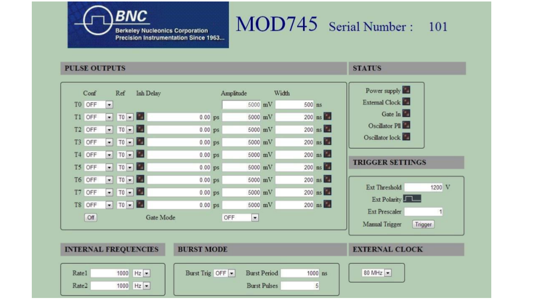
From that page, the user can configure each output pulse (amplitude, width, trigger, delay, inhibit, and delay reference), trigger settings, internal frequencies, external clock, and burst mode. On the first setting change, the user will be asked for a login and password (default login: BNC; default password: bnc). Status LEDs indicate which outputs are active or not, and Fault LEDs warn the user in case of errors. To refresh LED status, the user has to click on one of these LEDs. The manual trigger button is used to trigger a channel set to SS1, SS2, or LSS (single shot 1 and 2, and local single shot). Finally, the user can access the password setting page by typing in the address field: "Device IP/passwd.htm".

9Annex A: Pulse Results
High precision and auxiliary pulse results appear on the following figures.
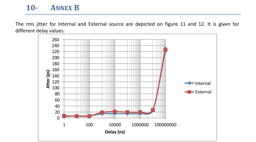
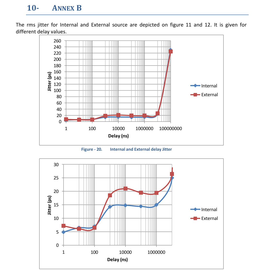
10Annex B: Delay Jitter
The RMS jitter for internal and external sources is depicted in the following figures. It is given for different delay values.
11Compliance and Contact
BNC Product Information for the People's Republic of China
This document provides product information as required by the People's Republic of China Electronic Industry Standard SJ/T11364-2006, Marking for Control of Pollution Caused by Electronic Information Products. The table below lists toxic or hazardous substances or elements contained in electronic information products (EIPs), including subassemblies, that exceed limits specified in SJ/T11363-2006.
| Component Name | Lead (Pb) | Mercury (Hg) | Cadmium (Cd) | Hexavalent chromium (Cr6+) | PBB | PBDE |
|---|---|---|---|---|---|---|
| Printed circuit card assembly | X | O | O | O | O | O |
| Metal enclosure | X | O | O | X | O | O |
O: Indicates that the toxic or hazardous substance contained in all of the homogeneous materials for this part is below the limit required in SJ/T 11363-2006. X: Indicates that the toxic or hazardous substance contained in at least one of the homogeneous materials used for this part is above the limit requirement in SJ/T 11363-2006.
In accordance with the requirements specified in SJ/T 11324-2006, all BNC EIPs sold in the People's Republic of China are marked with a pollution control marking. The environmentally friendly use period (EFUP) is the number of years from the date of manufacture that toxic or hazardous substances or elements contained in EIPs will not leak or mutate under the normal operating conditions described in the EIP user documentation. Manufacture dates of all BNC products are encoded into the product serial number. Contact your local sales office to obtain the manufacture date for your product.
Waste Electrical and Electronic Equipment (WEEE)
EU customers: at the end of the product life cycle, all products must be sent to a WEEE recycling center.
Support
Berkeley Nucleonics Corporation
2955 Kerner Blvd., San Rafael, CA 94901
Phone: (415) 453-9955
Email: info@berkeleynucleonics.com
Web: www.berkeleynucleonics.com
Model 745T User Manual · NUT 083, Ed. 1.0 · Print Code: 41025070