ICX-FieldHawk-U & ICX-FieldHawk-N USB / Networked Real-Time Spectrum Analyzers
A compact family of USB and Ethernet real-time spectrum analyzers spanning 4.5 GHz to 40 GHz. Strong RF performance, a unified API, and a full set of standard measurements, in a form factor built for embedded and automated test systems.
Document: ICX-MAN-FHUNX · Rev. preliminary · 2026
Branding and verification notes. This Product Manual is rebranded from a third-party SAN/SAM/NXN/NXM series source manual. The following assumptions were applied. Please confirm before publication.
Model mapping. The numeric part of each model is the source model number (frequency-derived) and is preserved, zero-padded to three digits. USB models (source SAN / SAM) map to the ICX-FieldHawk-U line with a U suffix. Networked / Ethernet models (source NXN / NXM) map to the ICX-FieldHawk-N line with a proposed N suffix. The economy tier carries no extra mark; the performance tier (source SAM / NXM) carries a -P performance designation, for example ICX-060U-P. The "-N" networked suffix and the "-P" performance designation are proposed conventions. verify.
Firmware rename. The source control software is renamed throughout to SpecICX-gen3, Berkeley Nucleonics' spectrum analysis firmware. Described functionality is unchanged.
Antenna accessories. External antennas are presented as accessories, not options, drawn from the ANT-100G / ANT-200G family. Confirm the part number. verify.
Specifications. All spec values are reproduced identically from the source for the same hardware. Tables were lightly regrouped for readability. Values remain preliminary pending verification against the published BNC datasheet. verify.
In-firmware branding. The SpecICX-gen3 screenshots in sections 2 and 3 are sourced from the original application. The vendor wordmark has been masked and relabeled to SpecICX-gen3. Recapture with the production BNC build before publication. verify.
1Overview
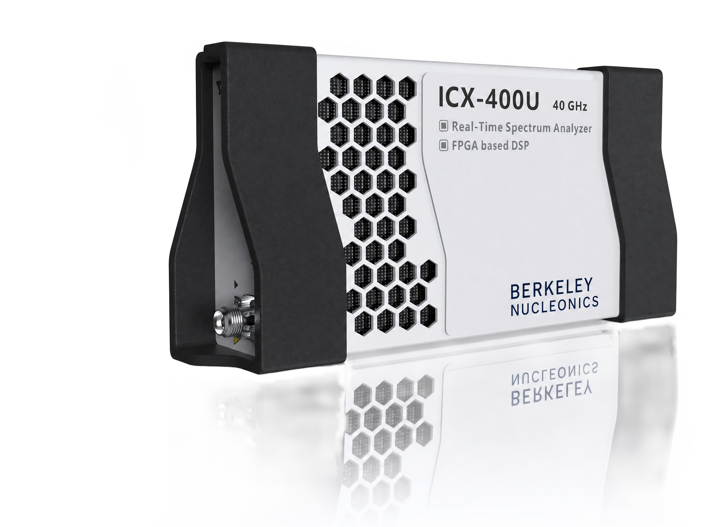
Figure 1-1. ICX-FieldHawk-U USB and ICX-FieldHawk-N networked real-time spectrum analyzers.
The ICX-FieldHawk-U and ICX-FieldHawk-N families are compact real-time spectrum analyzers that deliver excellent RF performance while holding cost down. Their miniaturized design integrates easily into automated test systems and preserves spectral purity, which makes them well suited to space- and cost-constrained applications where a full benchtop instrument would be impractical. The result is well-balanced performance, cost, and size across a wide range of models.
USB and Ethernet connectivity
The two lines differ in how they connect to the host. The ICX-FieldHawk-U line (USB) supports USB 3.0 and USB 2.0 over a single Type-C interface. The ICX-FieldHawk-N line (networked) connects over Ethernet and is compatible with 1000M and 100M networks. Beyond the host interface, the two lines are functionally aligned.
A wide range of models
The economy tier (the ICX-FieldHawk-U and ICX-FieldHawk-N base models) focuses on cost efficiency, with three frequency options: 4.5 GHz, 6.3 GHz, and 40 GHz. The performance tier (the -P designation) prioritizes RF performance, with 6.3 GHz and 8.5 GHz options. The combination of interface type, frequency range, and cost tier gives you a fully optimized choice for a wide variety of applications.
Unified API
Every series and model shares one consistent API. You can migrate between units, or from USB to Ethernet, without changing application code. Development is supported in C/C++, C#, Python, MATLAB, Qt, and LabVIEW, on both Windows and Linux.
Rich standard measurement functions
A rich set of advanced measurements ships as standard, including channel power, occupied bandwidth, X dB bandwidth, harmonic measurement, spectrum emission mask (SEM), AM and FM demodulation, and automatic phase noise analysis.
Key features
Frequency range: 9 kHz to 4.5 GHz, 6.3 GHz, 8.5 GHz, or 40 GHz, depending on model
SpecICX-gen3, Berkeley Nucleonics' spectrum analysis firmware, offers seven main operating modes: Standard Spectrum Analysis, IQ Streaming, Power Detection Analysis, Real-Time Spectrum Analysis, Phase Noise Measurement, Digital Demodulation (option), and Harmonics Analysis. Each mode reuses the same acquisition hardware, so switching between them takes no rewiring.
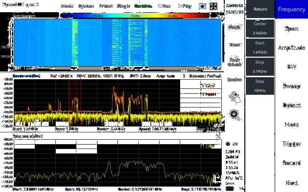
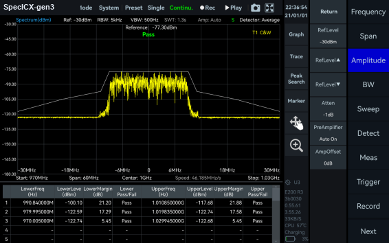
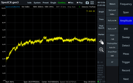
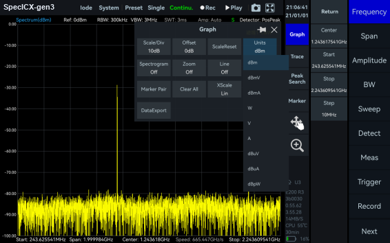
Standard Spectrum Analysis
This mode provides a wide range of measurement functions, including full-span spectrum sweep, channel power, OBW, ACPR, IM3, and SEM. It also supports spectrum recording and playback. Combined with auxiliary tools such as signal tracking, the peak table, and amplitude correction, it gives you a one-stop platform for thorough spectrum inspection.
Figure 2-1. Standard Spectrum Analysis mode in SpecICX-gen3.
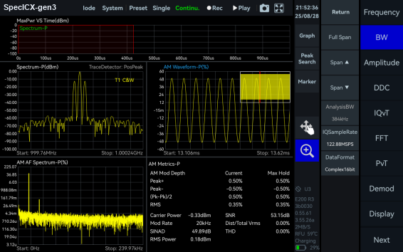
IQ Streaming
This mode supports up to 100 MHz of analysis bandwidth and acquires IQ data through multiple trigger methods. It provides IQ time-domain waveform display, spectrum and spectrogram views, AM and FM demodulation, and digital down conversion (DDC).
Figure 2-2. IQ Streaming mode in SpecICX-gen3.
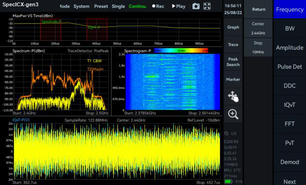
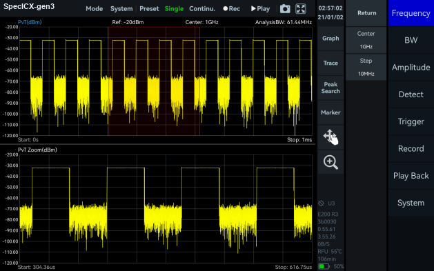
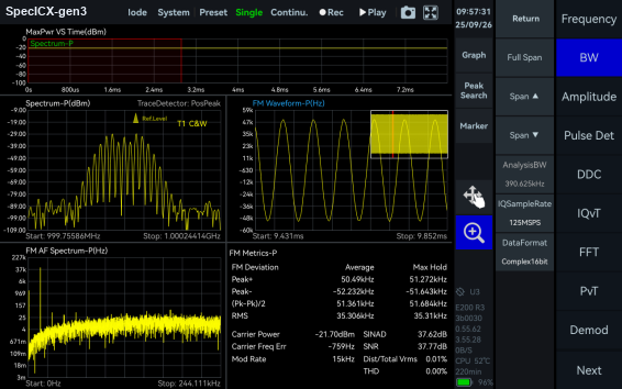
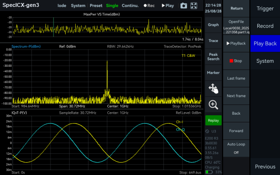
Power Detection Analysis
This mode detects and analyzes time-domain signals within the analysis bandwidth. It suits applications focused on in-band power versus time, such as pulse signal measurement.
Figure 2-3. Power Detection Analysis mode in SpecICX-gen3.
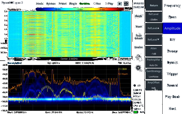
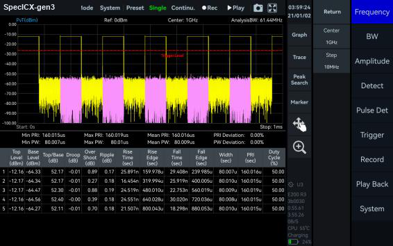
Real-Time Spectrum Analysis
This mode is powered by a high-speed FPGA-based FFT engine. The FFT is strictly gapless and overlap-free, which delivers true real-time monitoring across the full bandwidth with no missing samples between frames.
Figure 2-4. Real-Time Spectrum Analysis mode in SpecICX-gen3.
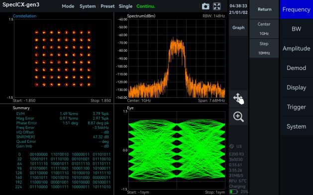
Digital Demodulation (option)
This mode supports 2ASK, 2FSK, 4FSK, GMSK, BPSK, QPSK, 8PSK, 16QAM, 64QAM, 128QAM, and 256QAM signals.
Figure 2-5. Digital Demodulation mode in SpecICX-gen3.
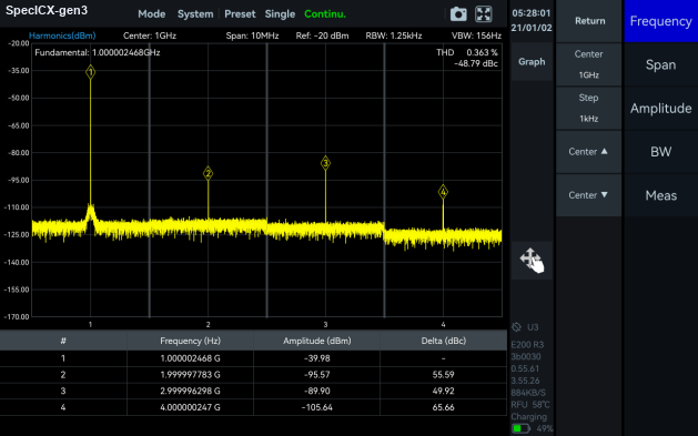
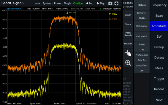
Harmonics Analysis
This mode detects and measures up to 10 harmonic components, including harmonic peaks, harmonic channel power, and total harmonic distortion.
Figure 2-6. Harmonics Analysis mode in SpecICX-gen3.
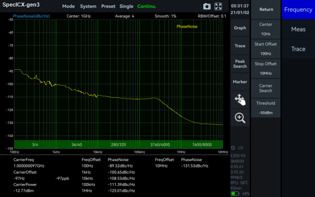
Phase Noise Measurement
This mode supports offset ranges from 1 Hz to 10 MHz for evaluating carrier phase stability. A built-in automatic carrier search locates the target carrier quickly, with no manual adjustment.
Figure 2-7. Phase Noise Measurement mode in SpecICX-gen3.
3Measurement Functions
The following measurements come standard in SpecICX-gen3 unless marked as an option. Each screenshot is captured from the firmware running on an ICX-FieldHawk analyzer.
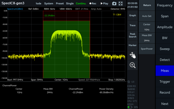
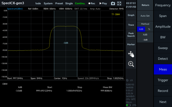
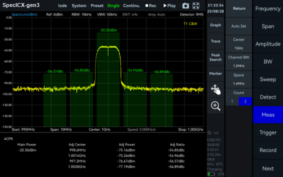
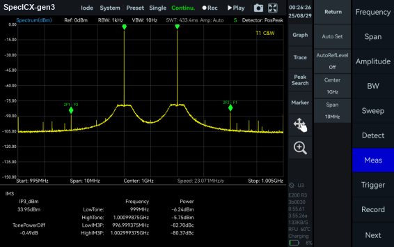
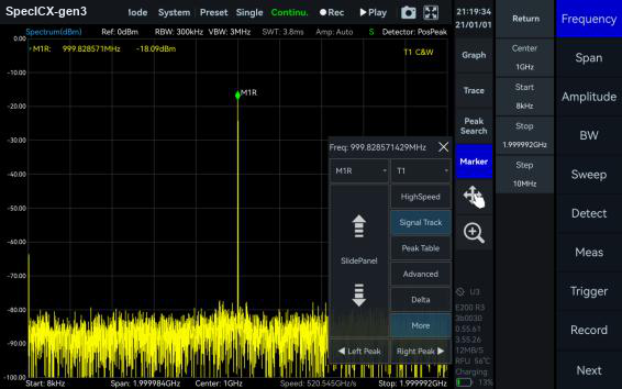
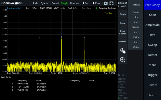
Figure 3-1. Channel Power.Figure 3-2. OBW (Occupied Bandwidth).Figure 3-3. ACPR (Adjacent Channel Power Ratio).Figure 3-4. IM3 (Third-Order Intermodulation).Figure 3-5. SEM (Spectrum Emission Mask).Figure 3-6. AM Demodulation.Figure 3-7. FM Demodulation.Figure 3-8. Pulse Detection (option).Figure 3-9. Antenna Factor.Figure 3-10. Amplitude Offset.Figure 3-11. Signal Track.Figure 3-12. Peak Table.Figure 3-13. Data Record and Playback.Figure 3-14. Multiple Unit Display.
4Frequency
Frequency range by model
USB model
Networked model
Frequency range
ICX-045U
ICX-045N
9 kHz to 4.5 GHz
ICX-060U
ICX-060N
9 kHz to 6.3 GHz
ICX-060U-P
ICX-060N-P
9 kHz to 6.3 GHz
ICX-080U-P
ICX-080N-P
9 kHz to 8.5 GHz
ICX-400U
ICX-400N
9 kHz to 40 GHz
Reference clock and stability
Parameter
Configuration
Specification
Reference clock
Standard
Internal or external
Frequency accuracy
TCXO (std.)
<1 ppm, manual correction available
Frequency accuracy
OCXO (opt 01)
<1 ppm, manual correction available
Frequency accuracy
GNSS-disciplined OCXO (opt 23 / 06)
<0.05 ppm, when locked to GNSS
Aging and temperature stability
TCXO (std.)
<1 ppm/year, <1 ppm
Aging and temperature stability
OCXO (opt 01)
<1 ppm/year, <0.15 ppm
Aging and temperature stability
GNSS-disciplined OCXO (opt 23 / 06)
<1 ppm/year, <0.05 ppm
5Spectrum Purity
SSB phase noise (dBc/Hz)
Offset
ICX-045 (1 GHz)
ICX-045 (4.5 GHz)
ICX-060 (1 GHz)
ICX-060 (6.3 GHz)
ICX-060-P (1 GHz)
ICX-060-P (6.3 GHz)
ICX-080-P (1 GHz)
ICX-080-P (8.5 GHz)
ICX-400 (1 GHz)
ICX-400 (40 GHz)
1 kHz
-103.4
-93.5
-105.2
-91.2
-107.5
-92.7
-110.3
-93.5
-99.0
-78.4
10 kHz
-111.3
-100.3
-110.4
-99.3
-114.2
-99.7
-120.0
-100.5
-107.5
-85.7
100 kHz
-109.3
-98.5
-110.5
-97.4
-112.5
-98.6
-120.1
-100.8
-107.7
-85.1
1 MHz
-129.5
-121.9
-130.1
-119.9
-132.8
-120.1
-131.4
-116.9
-122.7
-100.8
Carrier frequencies per column as labeled. Columns apply equally to the matching USB (-U) and networked (-N) variants.
<-65 dBc, at center frequency ± (N/M) × 125 MHz, N, M = 1, 2, 3, 4, 5…
IIP3 / IIP2 (dBm)
Model
Carrier
R.L. = 20 dBm
R.L. = 0 dBm
R.L. = -20 dBm
ICX-045
1 GHz
47.4 / 85.8
35.1 / 85.5
10.0 / 66.3
ICX-045
4.5 GHz
45.6 / 98.0
26.1 / 91.6
6.9 / 19.4
ICX-060
1 GHz
46.6 / 86.0
29.6 / 85.8
10.5 / 67.3
ICX-060
6.3 GHz
42.9 / 109.5
24.6 / 98.5
3.9 / 17.1
ICX-060-P
1 GHz
51.0 / 84.9
40.1 / 85.1
10.0 / 66.4
ICX-060-P
6.3 GHz
43.4 / 65.9
25.3 / 94.6
4.7 / 17.7
ICX-080-P
1 GHz
49.6 / 87.5
35.6 / 84.3
11.5 / 67.4
ICX-080-P
8.5 GHz
41.0 / 57.4
25.5 / 44.8
2.4 / 34.2
ICX-400
1 GHz
40.3 / 75.5
27.4 / 45.3
8.7 / 25.2
ICX-400
40 GHz
31.7 / 88.6
10.3 / 86.1
4.8 / 66.6
6Amplitude
Parameter
ICX-045 / ICX-060 / ICX-060-P / ICX-080-P
ICX-400
Display range
DANL to 23 dBm
DANL to 20 dBm
Reference level (R.L.)
-50 dBm to +23 dBm
-50 dBm to +20 dBm
Amplitude accuracy
9 kHz to 4.5 / 6.3 / 8.5 GHz: ±2.0 dB
9 kHz to 9.5 GHz: ±2.0 dB; 9.5 GHz to 40 GHz: ±3.0 dB
Max. input power (CW)
23 dBm (30 MHz to 4.5 / 6.3 / 8.5 GHz, preamp off); 10 dBm (9 kHz to 30 MHz or preamp on)
23 dBm (50 MHz to 40 GHz, preamp off); 10 dBm (9 kHz to 50 MHz or preamp on)
VSWR
30 MHz to 4.5 / 6.3 / 8.5 GHz: <2.5:1
90 MHz to 16 GHz: <2.0:1; 16 GHz to 40 GHz: <3.0:1
Max. DC voltage
±10 VDC
±10 VDC
IF in-band flatness
±2.0 dB
±2.0 dB
RF preamplifiers
Automatically turn on or forcibly turn off
Automatically turn on or forcibly turn off
7Display Average Noise Level (DANL)
DANL in dBm/Hz, RBW = 1 kHz. Columns apply equally to the matching USB (-U) and networked (-N) variants.
Band / R.L.
ICX-045 (-20 dBm)
ICX-045 (-50 dBm)
ICX-060 (-20 dBm)
ICX-060 (-50 dBm)
ICX-060-P (-20 dBm)
ICX-060-P (-50 dBm)
ICX-080-P (-20 dBm)
ICX-080-P (-50 dBm)
ICX-400 (-20 dBm)
ICX-400 (-50 dBm)
9 kHz to 1 MHz
-134.6
-150.3
-136.4
-147.9
-135.9
-148.5
-141.4
-151.7
-136.0
-145.8
1 MHz to 30 MHz
-140.2
-162.6
-139.7
-162.3
-140.7
-162.8
-154.2
-161.6
-153.7
-158.0
30 MHz to 3.0 GHz
-153.2
-163.5
-152.7
-164.8
-152.1
-163.9
-150.8
-167.1
-153.7
-158.0
3.0 GHz to 4.5 GHz
-155.2
-162.7
-157.1
-163.5
-151.3
-162.0
-155.6
-164.7
-154.1
-159.9
4.5 GHz to 6.3 GHz
-
-
-151.9
-160.4
-151.3
-162.0
-155.6
-164.7
-154.1
-159.9
6.3 GHz to 8.5 GHz
-
-
-
-
-
-
-144.0
-157.2
-154.1
-159.9
8.5 GHz to 19 GHz
-
-
-
-
-
-
-
-
-154.1
-159.9
19 GHz to 40 GHz
-
-
-
-
-
-
-
-
-145.2
-149.3
8Standard Spectrum Analysis
Parameter
ICX-045 / ICX-060 / ICX-060-P / ICX-080-P
ICX-400
RBW
0.1 Hz to 2.5 MHz
0.1 Hz to 10 MHz
VBW
0.1 Hz to 10 MHz
0.1 Hz to 10 MHz
Detector
PosPeak, NegPeak, Sample, Average, RMS, MaxPower
Data chart
SpecICX-gen3 provides spectrum, spectrogram, and historical trace
Measurements
Channel power, OBW, X dB bandwidth, ACPR, IM3
Sweep speed
Model
RBW = 250 kHz, FPGA, spur reject bypass
RBW = 250 kHz, FPGA, spur reject standard
RBW = 50 kHz, FPGA, spur reject bypass
RBW = 1 kHz, CPU, spur reject bypass
ICX-045U
186.0 GHz/s
86.9 GHz/s
79.0 GHz/s
5.7 GHz/s
ICX-045N
152.5 GHz/s
73.8 GHz/s
70.8 GHz/s
3.5 GHz/s
ICX-060U
444.5 GHz/s
209.4 GHz/s
157.3 GHz/s
6.2 GHz/s
ICX-060N
285.7 GHz/s
132.3 GHz/s
132.9 GHz/s
3.5 GHz/s
ICX-060U-P
793.3 GHz/s
382.7 GHz/s
242.2 GHz/s
5.9 GHz/s
ICX-060N-P
354.4 GHz/s
178.2 GHz/s
178.2 GHz/s
3.5 GHz/s
ICX-080U-P
822.1 GHz/s
359.2 GHz/s
230.8 GHz/s
5.8 GHz/s
ICX-080N-P
355.8 GHz/s
178.2 GHz/s
178.2 GHz/s
3.5 GHz/s
ICX-400U
1.1 THz/s
584.6 GHz/s
215.6 GHz/s
4.3 GHz/s
ICX-400N
657.4 GHz/s
330.8 GHz/s
166.3 GHz/s
3.4 GHz/s
9IQ Recording
Parameter
ICX-045
ICX-060
ICX-060-P / ICX-080-P
ICX-400
IQ sample rate (max.)
7.8125 MSPS
31.25 MSPS
125 MSPS
125 MSPS
Decimation factor
2ⁿ (n = 0 to 8)
2ⁿ (n = 0 to 10)
2ⁿ (n = 0 to 12)
2ⁿ (n = 0 to 12)
Burst recording bandwidth (max.)
6.25 MHz
25 MHz
100 MHz
100 MHz
Parameter
ICX-045, ICX-400, and networked ICX-060N / ICX-400N
ICX-060U
ICX-060-P / ICX-080-P (USB)
Continuous recording bandwidth (max.)
6.25 MHz
25 MHz
50 MHz
External trigger response
Maximum frequency response: 500 times/sec
Built-in memory depth is 128 Mbytes. Networked (-N) models cap continuous recording bandwidth at 6.25 MHz. Continuous-recording grouping reflects the source layout. verify per model.
10Detection Analysis
Parameter
ICX-045
ICX-060
ICX-060-P / ICX-080-P / ICX-400
Lowest time resolution
128 ns
32 ns
8 ns
Max. analysis bandwidth
6.25 MHz
25 MHz
100 MHz
Detector
PosPeak, NegPeak, Sample, Average, RMS, MaxPower
11Real-Time Spectrum Analysis
The FFT engine is implemented in FPGA. Frame compression and trace detection are supported, with no missing samples between FFT frames. FFT frame update rate = 109 ns / (N × D × lowest time resolution); POI = 2 × N × D × lowest time resolution, where N is FFT points (2048, 1024, 512, 256, 128, 64, 32) and D is the decimate factor (1, 2, 4, 8…).
Specification conditions. Specifications apply after start-up and a 10-minute warm-up; at 25 °C ambient (50 °C core); in standard spectrum analysis mode with spurious rejection standard on; with adequate heat dissipation to keep ambient and core temperature within the rated range. Sweep speed and DANL test conditions: MCU 0.55.57, FPGA 0.55.22, API 0.55.61.
14Inputs & Outputs
Port
ICX-045 / ICX-060 / ICX-060-P / ICX-080-P (USB)
ICX-FieldHawk-N (networked)
ICX-400U
External trigger input
Type-C, 3.3 V CMOS, high impedance
MMCX (F), 3.3 V CMOS, high impedance
Integrated in AUXIO, 3.3 V CMOS, high impedance
Trigger output
Type-C, 3.3 V CMOS
MMCX (F), 3.3 V CMOS
Integrated in AUXIO, 3.3 V CMOS
Port
ICX-045 / ICX-060 / ICX-060-P / ICX-080-P
ICX-400
RF input
SMA (F), impedance 50 Ω
2.92 mm (F), impedance 50 Ω
RF output
SMA (F), impedance 50 Ω
-
Reference clock input
MCX (F), amplitude ≥1.5 Vpp, impedance 330 Ω
MMCX (F), amplitude ≥1.5 Vpp, impedance 330 Ω
Reference clock output
Unavailable
Integrated in AUXIO, 3.3 V CMOS, programmable on/off
Antennas and physical add-ons drawn from the Berkeley Nucleonics antenna line.
Accessory
Description
Type
ANT-100G
Directional antenna, 500 MHz to 10 GHz
Antenna accessory
ANT-200G
Directional antenna, 500 MHz to 20 GHz
Antenna accessory
Omnidirectional antenna
External omnidirectional antenna, 400 MHz to 8000 MHz, gain <2 dBi
Antenna accessory
Antenna accessories. For BNC-supplied directional antennas, see the ANT-100G family (ANT-100G and ANT-200G). Confirm part numbers before quoting. verify.
16Built-In Signal Generator (OPT-110)
Parameter
ICX-045 / ICX-060 / ICX-060-P / ICX-080-P
Frequency range
100 kHz to 6.3 GHz, step 10 Hz
Power range
-50 dBm to 0 dBm, step 0.25 dB
VSWR
30 MHz to 6.3 GHz: <2.0:1
Non-harmonic spurs
<-50 dBc
Harmonics
Frequency range
Second harmonic
Third harmonic and above
100 kHz to 30 MHz
<-10 dBc
<-10 dBc
30 MHz to 1.6 GHz
<-10 dBc
<-10 dBc
1.6 GHz to 3 GHz
<-20 dBc
<-20 dBc
3 GHz to 3.2 GHz
<-20 dBc
<-20 dBc
3.2 GHz to 6.3 GHz
<-20 dBc
<-20 dBc
Leakage to receiver
Frequency range
Leakage
100 kHz to 30 MHz
>90 dBc
30 MHz to 3 GHz
>80 dBc
3 GHz to 6.3 GHz
>70 dBc
17Model Selection
The ICX-FieldHawk-U (USB) and ICX-FieldHawk-N (networked) lines share the same measurement engine and firmware. Choose the interface that fits your host, the frequency ceiling your work demands, and the economy or performance tier. The networked line adds AArch64 support and internal GNSS.
USB line, by frequency and tier (ICX-FieldHawk-U)
Specification
ICX-045U
ICX-060U
ICX-060U-P
ICX-080U-P
ICX-400U
Frequency range
9 kHz to 4.5 GHz
9 kHz to 6.3 GHz
9 kHz to 6.3 GHz
9 kHz to 8.5 GHz
9 kHz to 40 GHz
Tier
Economy
Economy
Performance
Performance
Economy
Max. analysis bandwidth
6.25 MHz
25 MHz
100 MHz
100 MHz
100 MHz
IQ sample rate (max.)
7.8125 MSPS
31.25 MSPS
125 MSPS
125 MSPS
125 MSPS
RF connector
SMA (F)
SMA (F)
SMA (F)
SMA (F)
2.92 mm (F)
Interface
USB 3.0 / 2.0
USB 3.0 / 2.0
USB 3.0 / 2.0
USB 3.0 / 2.0
USB 3.0 / 2.0
Networked line, by frequency and tier (ICX-FieldHawk-N)
Specification
ICX-045N
ICX-060N
ICX-060N-P
ICX-080N-P
ICX-400N
Frequency range
9 kHz to 4.5 GHz
9 kHz to 6.3 GHz
9 kHz to 6.3 GHz
9 kHz to 8.5 GHz
9 kHz to 40 GHz
Tier
Economy
Economy
Performance
Performance
Economy
Max. analysis bandwidth
6.25 MHz
25 MHz
100 MHz
100 MHz
100 MHz
Interface
1000M / 100M Ethernet
1000M / 100M Ethernet
1000M / 100M Ethernet
1000M / 100M Ethernet
1000M / 100M Ethernet
RF connector
SMA (F)
SMA (F)
SMA (F)
SMA (F)
2.92 mm (F)
AArch64 / internal GNSS
Yes
Yes
Yes
Yes
Yes
Naming note. The "-N" networked suffix and the "-P" performance designation are proposed conventions for the rebranded line. Final model names are subject to confirmation. verify.
Contact and ordering
To configure a unit, request a quote, or arrange a demonstration, contact Berkeley Nucleonics at info@berkeleynucleonics.com or 800-234-7858. Our team can help you match interface, frequency, and tier to your application.