1. General Description
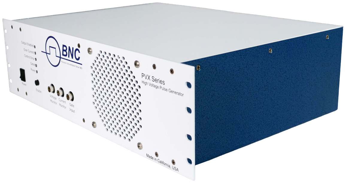
The BNC PVX-4151 pulse generator is a high-voltage solid-state pulser designed to drive capacitive loads such as grids, deflection, reflection, and acceleration plates.
The PVX-4151 generates an output voltage swing of 1500 volts, with an output current of 16 amperes peak and 0.05 amperes continuous. It produces very flat voltage pulses to DC into a capacitive load.
The PVX-4151 can generate single-ended output pulses from ground to +1500 V or from ground to −1500 V, and it can also generate pulses originating from a voltage offset from ground. This offset can be from −1500 V to +1500 V, with a maximum power-supply voltage differential (Vhigh − Vlow) of 1500 V or less.
2. Specifications
All specifications are measured into a 50 pF load connected with 6 feet (~1.8 m) of RG-62 (93 Ω) coaxial cable.
Input DC Voltage +V IN (Vhigh)
| Source | External |
|---|---|
| Absolute maximum value | +1500 volts |
| Relative maximum value | +1500 volts above −V IN level |
| Absolute minimum value | −1500 volts |
| Relative minimum value | 0 volts above −V IN level |
| Input connector | Type SHV, rear panel (+V IN) |
Input DC Voltage −V IN (Vlow)
| Source | External |
|---|---|
| Absolute maximum value | +1500 volts |
| Absolute minimum value | −1500 volts |
| Input connector | Type SHV, rear panel (−V IN) |
Output Pulse Voltage
| Maximum value | ±1500 volts (−V IN to +V IN) |
|---|---|
| Minimum value | 0 volts |
| Means of adjustment | Controlled by power-supply input voltages |
| Output connector | Type SHV, rear panel (OUTPUT) |
Gate
| Gate source | External |
|---|---|
| Gate input | +5 V ±1 V into 50 Ω |
| Gate rise time | <20 ns |
| Gate input connector | Type BNC, front panel |
Voltage Monitor
| Voltage monitor | 1000:1 into 1 MΩ, 20 MHz bandwidth limit |
|---|---|
| Connector | Type BNC, front panel |
Current Monitor
| Current monitor type | 10 A/V into 50 Ω, 20 MHz bandwidth limit |
|---|---|
| Connector | Type BNC, front panel |
Output Pulse Electrical Characteristics
| Pulse rise time | <25 ns at 1500 V (10%–90%, 50 pF load) |
|---|---|
| Pulse fall time | <25 ns (10%–90%) |
| Pulse width | <60 ns to DC, controlled by input gate |
| Pulse recurrence frequency | Single shot to 240 kHz, controlled by input gate (1) |
| Droop | <1% into a capacitive load |
| Maximum duty cycle | Continuous |
| Maximum power dissipation into a capacitive load (CV2F) | 150 watts, derated at 2 W/°C over 25 °C ambient (1) |
General
| Support power | 90 VAC to 240 VAC, 50/60 Hz |
|---|---|
| Dimensions (excluding connectors) | 19″ W × 5.2″ H × 13″ D (48.25 cm × 13.2 cm × 33 cm) |
| Weight (approximate) | 18 lbs (8.2 kg) |
These specifications are measured driving a 50 pF load connected with 6 feet of RG-62 cable, at 1500 V output. The PVX-4151 can drive loads of a few picofarads to several hundred picofarads of capacitance, limited by its maximum power-dissipation capability (1). At lower load capacitances and/or voltages less than 1500 V, the PVX-4151 can operate at continuous pulse recurrence frequencies above 240 kHz. The PVX-4151 can also drive resistive or inductive loads, within limitations. Contact BNC for additional information and applications assistance.
(1) The power dissipated in the PVX-4151 when driving a capacitive load is defined by the formula CV2F, where C is the total load capacitance (including the load, the interconnect cable, and the internal capacitance of the PVX-4151), V is the pulse voltage, and F is the pulse repetition frequency. For these calculations, the internal capacitance of the PVX-4151 is 200 pF and RG-62 cable is 13 pF/foot. Given the maximum dissipation of 150 W, the maximum load capacitance, frequency, and/or voltage at which the PVX-4151 can operate can be approximated using this formula. This formula also approximates the high-voltage power-supply requirements needed to drive a given load at a specific voltage and frequency. It is not applicable when driving resistive or inductive loads.
3. Safety
The high voltage of this device dictates the use of caution when operating or servicing this equipment. The following is a summary of general safety precautions that must be observed during all phases of operation and repair of the PVX-4151.
3.1 Operating Safety Summary
The safety information in this summary is for both operating and servicing personnel. Specific warnings may be found throughout this manual but may not appear in this summary.
3.1.1 Power Source
The PVX-4151 is designed to operate from a power source that will not apply more than 240 volts between the supply conductors or between either supply conductor and ground. A protective grounding connection by way of the grounding conductor in the AC power cord is essential.
3.1.2 Grounding
The PVX-4151 is grounded through the grounding conductor of the AC power cord. To avoid electrical shock, plug the PVX-4151 into a properly wired receptacle before making connection to any input or output connectors. Use only a power cord that is in good condition.
3.1.3 Cover Removal
3.1.4 General Operating Precautions
Do not remove the input or output cables while the pulser is in operation. Never short-circuit the output of the unit. Failure to observe these precautions can result in potential electric shock to personnel, arcing, and damage to the connectors and system.
The top cover of the PVX-4151 is not safety interlocked. Extreme caution should be exercised when removing the cover. Any pulsed-power system is capable of random triggering via transients. Therefore, when the PVX-4151 is turned on, or dangerous voltage is present in the chassis, assume it is possible to get a pulse on the output connector.
3.2 Servicing Safety Summary
The PVX-4151 contains dangerous voltages and stored energy. BNC strongly recommends that all repairs and adjustments be performed by factory-qualified personnel. BNC will not be responsible for personal injury or damage to the driver that occurs during repair by any party other than the factory.
3.2.1 Servicing Procedure
Do not perform internal repair or adjustments unless another person capable of rendering first aid and resuscitation is present.
3.2.2 Internal Energy Storage
4. Operating Considerations
4.1 Output Cabling
The PVX-4151 is designed to drive capacitive loads with fast rise times. Since the current out of the PVX-4151 is limited, the lower the capacitance, the faster the rise time. Given fixed load characteristics, only the interconnecting cable type and length will vary the output capacitance.
The unit is supplied with a 6-foot length of RG-62 coaxial cable, which has a capacitance of 13.5 pF per foot. The unit is series terminated in the characteristic impedance of this cable, which is 93 Ω. BNC recommends that the shortest length of cable possible be used to ensure the fastest possible rise times and best pulse fidelity.
4.2 Load Simulation
This unit was tested with a 50 pF capacitive load connected to the output with 6 feet of RG-62 coaxial cable.
4.3 Trigger Input
An input trigger of +5 V ±1 V into 50 Ω with a rise time of <20 ns is required to gate on the PVX-4151. Departure from these values can result in a loss of performance. These trigger requirements are met by any high-quality low-voltage pulse generator. The trigger should be set to +5 V ±1 V into 50 Ω before the trigger cable is attached to the PVX-4151 trigger input. The input trigger amplitude should be set using a 50 Ω load (for example, a 50 Ω scope input) before connecting it to the PVX-4151. If the trigger input is greater than +5 V into 50 Ω, pulse stretching can occur.
4.4 Pulse Voltages +V IN and −V IN
The PVX-4151 is rated at a maximum pulse output voltage of ±1500 VDC. Proper precautions should be taken by the user to ensure that the maximum voltage is not exceeded.
4.5 Output Pulse Considerations
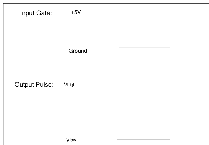
The PVX-4151 can generate single-ended output pulses from ground to +1500 V or from ground to −1500 V, and it can also generate pulses originating from a voltage offset from ground. This offset can be from −1500 V to +1500 V, but the maximum power-supply voltage differential (Vhigh − Vlow) should never exceed 1500 V. The Vhigh supply should always be equal to or greater than the Vlow supply, but never greater than 1500 V above the Vlow supply. Therefore the Vlow supply may be set to any voltage between −1500 V and +1500 V, and the Vhigh supply may be set to any voltage between −1500 V and +1500 V, but the voltage difference between Vlow and Vhigh should never exceed 1500 V. If the unit is operated with a single power supply (single-ended), the unused power-supply input should be grounded.
When the input gate is high, the Vhigh supply is connected to the output. When the input gate is low, the Vlow supply is connected to the output. Therefore the PVX-4151 can be used to generate a negative-going pulse by logically inverting the input gate, so that the input gate is high until the unit is pulsed. When the input gate goes low, the Vlow supply is connected to the output, thereby generating a negative-going pulse (see the example in the figure below).
4.6 Controls and Indicators
4.6.1 Power Switch and LED
The switch labeled POWER controls all AC power in the chassis. The LED labeled POWER above the switch illuminates when AC power is turned on.
4.6.2 Enable Switch and LED
The enable switch enables and disables the pulse output. When the switch is on, the output is enabled and the OUTPUT ENABLED LED above the switch is illuminated. If the enable LED is not illuminated, the PVX-4151 will not generate an output pulse. The external interlock circuit (on the rear-panel DSUB connector) must be satisfied before the PVX-4151 can be enabled. If the enable LED does not illuminate when the enable switch is pressed, confirm that the external interlock circuit is satisfied.
4.6.3 Gate Connector
The BNC connector labeled GATE is the input to gate the pulser. The input should be +5 V into 50 Ω, with a rise time less than 20 ns. The output pulse width and frequency are controlled by the input gate's width and frequency.
4.6.4 Gated LED
The LED labeled GATED illuminates when a gate signal of the appropriate amplitude and width to gate the pulser is received. If the GATED LED is not illuminated, the PVX-4151 will not generate an output pulse.
4.6.5 Over Current LED
The LED labeled OVER CURRENT illuminates if the output pulse current exceeds 15 A. If this LED illuminates, the pulse output will be inhibited for 6–7 milliseconds. If the LED illuminates continuously, the cause of the over-current fault should be corrected before attempting to operate the pulser.
4.6.6 Control Error LED
The LED labeled CONTROL ERROR illuminates if the input gate frequency exceeds ~250 kHz. If this LED illuminates, the pulse output will be inhibited. Reduce the frequency of the input gate before attempting to operate the pulser.
4.6.7 Current Monitor
The BNC connector labeled I MON provides a 10 A/V monitor of the output current. This monitor should be terminated into 50 Ω, such as the 50 Ω input of an oscilloscope.
4.6.8 Voltage Monitor
The BNC connector labeled V MON provides a 1 V per 1000 V monitor of the output pulse. This monitor should be terminated into 1 MΩ, such as the 1 MΩ input of an oscilloscope. Note that due to the 20 MHz bandwidth limit on the V-MON, the rise and fall times will not be accurate.
4.7 Remote Control
The PVX-4151 has the capability to be operated through remote controls. The following table provides the pinout of the 15-pin DSUB connector on the rear panel.
| Pin | Function | Description |
|---|---|---|
| 1 | GND | Ground |
| 2 | GND | Ground |
| 3 | GND | Ground |
| 4 | GND | Ground |
| 5 | GND | Ground |
| 6 | NC | No connect |
| 7 | NC | No connect |
| 8 | NC | No connect |
| 9 | ENABLE | Unit enables, disables, and resets on a low-to-high edge |
| 10 | INVERT | Low internally inverts the gate pulse |
| 11 | REMOTE | Low for remote operation |
| 12 | INTERLOCK | Low to satisfy the interlock |
| 13 | AUTO RESET | Low for enabling auto reset |
| 14 | NC | No connect |
| 15 | NC | No connect |
The control pins on the remote connector are internally pulled high. For remote operation, the REMOTE pin should be pulled low. This disables the front-panel ENABLE switch to prevent local operation. The remote ENABLE, INTERLOCK, INVERT, and AUTO RESET inputs are always active, regardless of the state of the REMOTE signal. If the ENABLE signal is momentarily pulled low, the unit will be enabled, or a fault will be cleared, on the rising edge of that signal. If the INVERT pin is pulled low, the gate pulses going into the unit will be inverted internally, so the output pulse will be inverted from that of the input gate.
The AUTO RESET function allows the user to choose how to clear faults. If the AUTO RESET pin is pulled low, the unit will reset itself 6 ms after a fault occurs, such as an over-current or interlock fault. If AUTO RESET is not pulled low, the user will have to reset faults manually. To reset a fault, the ENABLE pin should be pulled low two times: once to reset the fault and a second time to enable the output. If the user does not want to operate in remote mode, pins 4 and 12 and pins 5 and 13 should be jumpered together. This satisfies the interlock and enables the auto-reset function.
The PVX-4151 is shipped with a mating DSUB connector installed, with pins 4 and 12 and pins 5 and 13 jumpered. As shipped, remote operation is disabled. This connector must be installed in order to satisfy the interlock circuit; if it is not installed, the unit cannot be enabled.
5. Preparation for Use
5.1 General
After unpacking, initial inspection and preliminary electrical-check procedures should be performed to assure that the unit is in good working order. If it is determined that the unit is damaged, the carrier should be notified immediately. Repair problems should be directed to the service department, Berkeley Nucleonics Corp. (BNC).
5.2 Initial Inspection
- Inspect the unit for exterior mechanical damage.
- Inspect the power input cord and input power module for obvious signs of damage.
5.3 Electrical Installation
Standard units are shipped ready for use with a nominal 100 to 240 VAC input.
5.3.1 Input Power Cord
The input power cord terminates externally in a three-prong polarized plug. The unit chassis is wired to the plug through the line cord; therefore, insertion of the plug into a compatible receptacle hooked up to a grounded input will automatically ground the unit. The unit should not be operated without a grounded AC input.
5.4 Electrical Check
Before proceeding, review the precautions in Section 3.
5.4.1 Power-Up
- Install the mating rear-panel DSUB connector supplied with the unit. This connector has pins 4 and 12 and pins 5 and 13 jumpered, so as shipped, remote operation is disabled. This connector must be installed in order to satisfy the interlock circuit; if it is not installed, the unit cannot be enabled. To operate the PVX-4151 remotely or to use an external interlock, wire the DSUB connector accordingly (see Section 4.7, Remote Control).
- Before connecting the pulse generator to the PVX-4151, set up the pulse-generator output to deliver a +5 V pulse (±1 V) into 50 Ω, with a rep rate of approximately 500 Hz and a pulse width of 1 µs.
- Connect the positive output power supply to the rear-panel SHV connector labeled +V IN. Connect the negative output power supply to the rear-panel SHV connector labeled −V IN. For +1500 V single-ended output, −V IN must be connected to ground. The power-supply input should be grounded if no power supply is connected. Ensure that both power supplies are turned off.
- Plug the power cord into the AC power input. Ensure the power switch on the rear of the instrument is set to the ON position, then turn the unit on using the power switch on the front panel. The POWER indicator LED should turn on, indicating that the PVX-4151 is operational. If this does not occur, unplug the unit from AC power and refer to Section 7, Troubleshooting.
- Connect the pulse generator to the front-panel BNC connector of the PVX-4151 labeled GATE.
- The PVX-4151 powers up in a faulted condition. Once the gate is connected, the fault should clear within 5 seconds.
- Enable the pulses by pressing the ENABLE button. The green OUTPUT ENABLED LED should light. If the above-mentioned fault is not clear, the output will not be enabled until the 5-second time limit has expired and the ENABLE button is pressed again.
- Connect an appropriate load to the rear-panel SHV output connector.
- The output voltage can be monitored in two ways: by connecting an appropriate high-voltage probe to the output load (using an attenuator if necessary), or, more easily, by attaching a 50 Ω coax to the V-MON connector on the front panel. Note that due to the 20 MHz bandwidth limit on the V-MON, the rise and fall times will not be accurate.
- Slowly turn up the high-voltage power supplies. The PVX-4151 should produce an output pulse, with a pulse width and pulse recurrence frequency following that of the incoming trigger.
- If there is no output from the PVX-4151, or the output is severely distorted, turn off the high-voltage power supplies. Leave the PVX-4151 connected to the AC input without pulse voltage and with all connectors in place for approximately five minutes to bleed off the stored energy, then disconnect the AC power and refer to Section 7, Troubleshooting.
6. Operating Instructions
This section provides basic operating instructions for the PVX-4151.
- To avoid personal injury, do not remove the covers and do not operate the PVX-4151 while the covers are removed. The covers do not contain safety interlocks.
- Do not remove the input or output cables while the driver is in operation. Never short-circuit the pulse-voltage output of the pulser. Failure to observe these precautions can result in potential electric shock to personnel, arcing, and damage to the connectors and system.
- The covers of the PVX-4151 are not safety interlocked. Extreme caution should be exercised when removing the covers.
- Pulsed-power systems are capable of random triggering via transients. When the PVX-4151 is turned on, or voltage is present in the chassis, assume it is possible to get a pulse on the output connector.
6.1 Power-Up Procedures
The unit should be powered up using the procedures detailed in Section 5.4.1. When this is accomplished, the driver can be adjusted for the particular application through the following procedure:
- Monitor the output of the PVX-4151 on an oscilloscope using a high-voltage probe connected to the output load, or with a coax attached to the V-MON on the front panel. Set the output amplitude of the PVX-4151 to the desired level by adjusting the output voltage of the high-voltage power supplies.
- Set the output pulse width and pulse recurrence frequency by varying the controls of the input pulse generator. The output pulse width should be set by monitoring the output of the PVX-4151. The output pulse voltage will follow the input trigger, but will not replicate in time the exact duration of the input trigger due to system propagation delay.
6.2 Power-Down Procedures
- Set the controls of the high-voltage power supplies to zero.
- Turn off the high-voltage power supplies.
- Leave the PVX-4151 connected to the AC input without high voltage and with all connectors in place for approximately five minutes to bleed off the stored energy.
- Disconnect the AC power to the unit.
7. Troubleshooting
7.1 Troubleshooting Procedures
Before attempting to service or troubleshoot the PVX-4151, review the servicing safety summary in Section 3. The power MOSFETs used in the PVX-4151 are mounted on the printed circuit board. In the unlikely event that the MOSFETs need to be replaced, it is highly recommended that the unit be returned to the factory for servicing. The table below summarizes potential problems and their solutions. If these recommendations do not resolve the problem, BNC customer service can be contacted for further assistance.
| Symptom | Solutions |
|---|---|
| POWER LED does not illuminate | AC power not plugged in. Fuse(s) are blown (see fuse-replacement instructions in Section 7.1.1). |
| Cannot enable output | External remote interlock circuit is not satisfied. Output is not enabled. |
| No output pulse | No input trigger. Input trigger voltage too low. Input trigger pulse width too short (increase width). Input trigger frequency too high (reduce frequency). No high voltage (check power supplies). Output not connected correctly (check all cables and connections). Pulser is damaged (contact BNC customer service). |
7.1.1 Fuses
| Fuse location | Fuse value |
|---|---|
| AC entry module | 3 A, 250 VAC fast blow |
7.2 Factory Service
If the procedures above fail to resolve an operational problem, please contact the factory for further assistance:
Berkeley Nucleonics Corp., San Rafael USA
Call: (415) 453-9955
Email: info@berkeleynucleonics.com
8. System Failure Modes
The PVX-4151 is capable of generating large-amplitude current pulses with very fast rise and fall times. There is limited over-current or over-voltage protection circuitry, and it is the user's responsibility to assure that the interconnect cables and load do not create transients, over-current, or over-voltage conditions that could damage the PVX-4151. Failure to do so voids the warranty.
8.1 Over-Current Failure
When the output is shorted, the PVX-4151 can deliver in excess of 16 A of current (depending on cabling, pulse power-supply setting, and so on). A current pulse of this magnitude exceeds the driver's specifications. If allowed to operate into a short for an extended period of time, damage to the unit, load, and/or associated cabling may result.
9. Warranty
There are no warranties, express or implied, including any implied warranty of fitness for a particular purpose nor any implied warranty of merchantability made by Berkeley Nucleonics Corp. (BNC) except as follows:
BNC warrants equipment manufactured by it to be free from defects in materials and/or workmanship under conditions of normal use for a period of one year from the date of shipment to the purchaser. BNC will repair or replace, at BNC's option, any product manufactured by it which is shown to be defective or fails to perform within specifications within one year from the date of shipment to the purchaser. OEM, modified, and custom items of equipment are similarly warranted for a period of ninety (90) days from the date of shipment to the purchaser.
Equipment claimed to be defective must be returned, transportation prepaid, to BNC's factory in Fort Collins, Colorado within the warranty period. Returns must be preauthorized by contact with BNC's customer service department. Written documentation of such preauthorization shall be included with the returned item. At BNC's discretion, BNC may elect to repair or replace the equipment claimed to be defective, or refund the original purchase price plus taxes and transportation charges incurred by the purchaser.
This warranty shall not apply to any product that has been (1) repaired, worked on, or altered by persons unauthorized by BNC; (2) subjected to misuse, neglect, or damage by others; or (3) connected, installed, adjusted, or used in a manner not authorized in the instructions or specifications furnished by BNC.
This warranty is the purchaser's sole remedy for claimed defects in the equipment sold or manufactured by BNC. BNC's liability to the purchaser is limited to the repair or replacement of the claimed defective equipment or, at BNC's option, refund of the purchase price, taxes, and transportation charges incurred by the purchaser. BNC will not be responsible for or liable to the purchaser for consequential losses or damages asserted to be attributable to a claimed defect in the equipment provided.
Changes made by BNC in the design or manufacture of similar equipment that are effected subsequent to the date of shipment of the warranted equipment to the purchaser are reflective of BNC's program of constant product development and improvement and shall not be construed as an acknowledgment of deficiency in the product shipped to the purchaser. BNC is under no obligation to make any changes to product previously shipped.
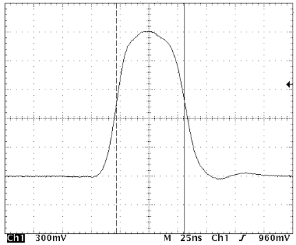
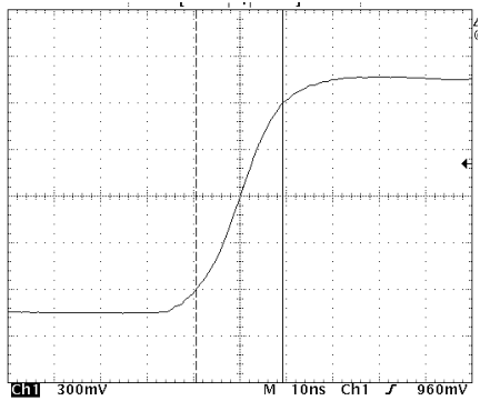
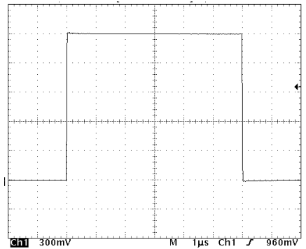
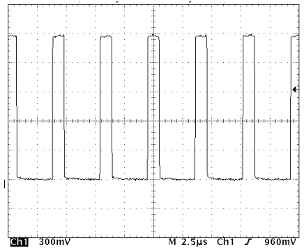
Appendix: Typical Output Waveforms