1Overview
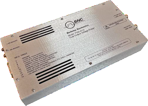
The Berkeley Nucleonics PVM-4210 is a compact, OEM-style dual-output high voltage pulse generator module. It provides two simultaneous differential voltage pulses of up to plus or minus 950 V, a 1,900 V differential swing, with rise and fall times under 25 ns and pulse widths continuously adjustable from under 50 ns to DC. The module operates on +24 VDC to +28 VDC support power and includes integrated DC high voltage power supplies, so it works as a complete pulser solution out of the box.
The PVM-4210 is optimized for differential drive of deflection plates used in the electrostatic modulation of particle beams in time-of-flight mass spectrometers and accelerators. The same module also drives Pockels cells, Q-switches, electrodes, microchannel plates, acoustic transducers, image intensifiers, and photomultiplier tubes. Where a system needs two fast, opposite-polarity pulses referenced to ground, the PVM-4210 supplies them from one board.
The design is direct-coupled and all-solid-state. It uses air as the primary insulating medium and is not potted, which keeps the module serviceable. A complete pulser, with high voltage supplies, energy storage, and output network on board, needs no series or shunt resistors, no matching networks, and no external capacitor banks.
2How It Works
The PVM-4210 contains two pulse output channels controlled by common control logic. On a gate signal both channels pulse simultaneously: one channel swings from ground to +HV, the other from ground to -HV. Connect each output to the electrodes of a Pockels cell or Q-switch, or to a pair of deflection plates, and the two channels together produce a 1,900 V differential pulse across the load. Outputs may also be inverted to pulse from the HV potential down to ground.
The width and frequency of the output pulses follow the TTL input gate. Each channel amplitude is independently adjustable from 0 to 950 V using screwdriver-adjustable potentiometers on the end panel, so the two polarities can be trimmed to match a given electrode geometry or balanced exactly for symmetric deflection.
Each channel uses a half-bridge, totem-pole design. This gives equally fast rise and fall, low power dissipation, and virtually no overshoot, undershoot, or ringing. Over-current detection and shut-down circuitry protects the module against arcs and shorts at the load. Because the high voltage supplies, energy storage, and output network are all built in, the PVM-4210 is a complete pulser solution. It needs no series or shunt resistors, no matching networks, and no external capacitor banks.
3Specifications
All specifications are preliminary and subject to verification against the published BNC datasheet.
| Parameter | Specification |
|---|---|
| Output Voltage | 0 to +950 V ±5 V (Channel 1); 0 to -950 V ±5 V (Channel 2) |
| Output Voltage Adjustment | Screwdriver-adjustable potentiometers, end panel |
| Pulse Width | <50 ns to DC, measured FWHM, controlled by input gate |
| Pulse Rise and Fall Time | ≤25 ns, 10% to 90% |
| Pulse Recurrence Frequency | Single-shot to >20 kHz continuous, 5 MHz burst, controlled by input gate |
| Pulse Droop | <1% |
| Over/Undershoot | <5% |
| Jitter | <1 ns shot-to-shot |
| Throughput Delay (leading edge of input gate to leading edge of output pulse) | 93 ns typical, continuous |
| Maximum Average Power (per channel) | 4 W |
| Pulse Output Connectors | SHV, end panel |
| Output Cables | 12 in (~30 cm) Belden 8218 75 Ω coaxial cable |
| Gate Source | External, TTL into 50 Ω; gate input rise time <20 ns; connector DSUB, end panel |
| Support Power | 24 VDC to 28 VDC @ 600 mA maximum current (1 A needed for high-frequency pulses when both negative and positive outputs are used at 950 V) |
| Dimensions (excluding connectors) | 5.75 in W x 1.75 in H x 11.5 in D (146 mm W x 44.5 mm H x 292 mm D) |
| Weight (approximate) | 41 ounces (1.16 kg) |
Power dissipation and capacitive loads
For a capacitive load, the power per channel follows C·V²·F, where C is the total load capacitance, V is the pulse voltage, and F is the repetition frequency. The total load capacitance is the sum of the load itself, the interconnect cable, and the internal capacitance of the PVM-4210. The module contributes 125 pF, and the Belden 8218 output cable adds 21.5 pF per foot.
With a maximum supply capability of 4 W (4 mA) per channel, the maximum combination of load capacitance, frequency, and voltage can be approximated from this formula. At lower load capacitances, or at voltages below 950 V, the PVM-4210 can run at continuous rates above 20 kHz. The formula applies to capacitive loads only. It does not apply to non-capacitive, resistive, or inductive loads.
4Monitoring & Front Panel
The PVM-4210 keeps its user interface on the end panel, where every connection and adjustment is reachable without opening the module. There are no front-panel displays to read and no menus to navigate. Setup is physical and direct.
High voltage outputs
The two pulse outputs terminate in SHV connectors on the end panel, one for the positive channel and one for the negative channel. Each output ships with a 12 in (~30 cm) length of Belden 8218 75 Ω coaxial cable. Channel 1 swings from 0 to +950 V and Channel 2 from 0 to -950 V, so the pair drives a deflection-plate or Pockels-cell load with a 1,900 V differential pulse.
Gate input
A DSUB connector on the end panel accepts the external gate. The gate is TTL into 50 Ω with an input rise time under 20 ns. The width and frequency of the output pulses follow this gate, so the timing of every pulse is set by the controlling system, not by the module. Driving the gate high enables the outputs; releasing it returns the channels to their rest state.
Amplitude trim
Each channel amplitude is set with a screwdriver-adjustable potentiometer on the end panel, independently from 0 to 950 V. This lets an integrator balance the two polarities for symmetric deflection, or offset them to suit a particular electrode geometry, then lock the setting in place for repeatable operation.
Protection
Over-current detection and shut-down circuitry guards both channels against arcs and shorts at the load. If a fault draws excess current, the affected channel shuts down rather than stressing the output stage. The half-bridge, totem-pole output stages deliver equally fast rise and fall with low power dissipation and virtually no overshoot, undershoot, or ringing.
5Applications
The PVM-4210 was designed for the differential drive of deflection plates that electrostatically modulate particle beams. Its primary home is in time-of-flight mass spectrometers and accelerators, where two fast, opposite-polarity pulses gate or steer an ion beam. The same dual-output architecture suits a broad set of high voltage pulsing tasks across photonics, physics, and detector instrumentation.
- Time-of-flight mass spectrometry. Differential drive of deflection plates for electrostatic modulation and beam gating.
- Accelerators. Electrostatic deflection and beam steering with synchronized positive and negative pulses.
- Pockels cells. Fast switching for electro-optic modulation and pulse picking.
- Q-switches. Pulsed drive for laser cavity Q-switching.
- Electrodes and deflection plates. Direct differential drive for a 1,900 V swing across the load.
- Microchannel plates. Gated high voltage for detector timing.
- Acoustic transducers. High voltage pulse excitation.
- Image intensifiers. Gating and modulation of intensified imaging stages.
- Photomultiplier tubes. Fast gating and protection pulsing.
6Ordering Information
| Model | Description |
|---|---|
| PVM-4210 | Dual Output High Voltage Pulse Generator Module |
Contact
For a quote, configuration help, or application support, reach the Berkeley Nucleonics team.
Email: info@berkeleynucleonics.com
Phone: 800-234-7858