1Overview
The Berkeley Nucleonics PVM-1001 is an adjustable pulsed voltage source built for fast, repeatable high-voltage pulses. It drives a 50 ohm resistive load from 0 V to 950 V in less than 10 ns rise time, with pulse widths from 55 ns to 10,000 ns and repetition rates to 1 MHz. In burst mode it reaches 5 MHz. The module turns a static high-voltage supply into a sharply switched pulse train, which is what fast gating and timing applications need.
The PVM-1001 ships in two polarities. The PVM-1001-P produces positive voltage pulses and requires an external positive HV power supply. The PVM-1001-N produces negative pulses and requires an external negative supply. Both share identical 5 MHz burst capability, so the polarity choice follows your load and bias scheme rather than your speed budget.
Output pulse width and frequency are set by an external trigger source. That keeps the module compatible with the timing electronics already on your bench, and it lets the PVM-1001 follow complex patterns without on-board sequencing. Typical work includes instrument calibration, component testing, beam steering, and PMT and MCP gating.
2How It Works
The PVM-1001 sits between a high-voltage DC source and a 50 ohm load. You connect a DC supply at or below 975 V (positive for the -P, negative for the -N) to the rear-panel MHV HV input. The module switches that potential to the rear-panel MHV output under the control of the front-panel trigger, producing a clean pulse with a sub-10 ns rising edge.
Timing comes entirely from the external trigger. A trigger applied to the front-panel SMB connector defines both pulse width and repetition rate. The trigger logic is direct: 0 V holds the output off, and 5 V turns the output on, gating the high voltage through to the load. Pulse widths from 55 ns to 10,000 ns and rates to 1 MHz cover most fast-pulse work, and burst mode extends the rate to 5 MHz for short, high-density sequences.
For the HV input to keep up with the load, the supply must deliver more power than the output draws. The requirement is straightforward: HV input power must exceed output power plus 5 W of headroom, and the supply should hold a compliance voltage about 25 V above the desired output. Refer to the safe-operating-area (SOA) graphs in the published datasheet before running near the 208 W maximum output power.
3Specifications
The following tables cover the positive module (PVM-1001-P), the negative module (PVM-1001-N), and the trigger and general specifications common to both. All specifications are measured driving a 50 ohm load, with a 1500 W, 50 ohm resistive load connected through 3 feet of RG-58 coax. Values are preliminary and subject to verification against the published BNC datasheet.
PVM-1001-P (Positive)
| Parameter | Specification |
|---|---|
| Input HV power supply requirement | ≤ 975 VDC positive source; HV input power > output power + 5 W |
| Output voltage range | 0 V to +950 V |
| Output droop | < 10 V/µs |
| Voltage overshoot | ≤ 10% (900 to 950 V); ≤ 12% (700 to 899 V); ≤ 14% (400 to 699 V); ≤ 15% (100 to 399 V); ≤ 17% (50 to 99 V) |
| Rise time | ≤ 8 ns @ 200 to 950 V; ≤ 10 ns @ 50 to 199 V |
| Fall time | ≤ 50 ns @ 450 to 950 V; ≤ 80 ns @ 200 to 449 V; ≤ 130 ns @ 50 to 199 V |
| Polarity | Positive |
| Compliance voltage | 25 V above desired output voltage |
| Maximum output power | 208 W (refer to SOA graphs) |
PVM-1001-N (Negative)
| Parameter | Specification |
|---|---|
| Input HV power supply requirement | ≤ -975 VDC negative source; HV input power > output power + 5 W |
| Output voltage range | 0 V to -950 V |
| Output droop | < -10 V/µs |
| Voltage overshoot | < 10% (-800 to -950 V); < 12% (-150 to -799 V); < 20% (-50 to -149 V) |
| Rise time | ≤ 9 ns @ -500 to -950 V; ≤ 10 ns @ -200 to -499 V; ≤ 12 ns @ -50 to -199 V |
| Fall time | ≤ 50 ns @ -450 to -950 V; ≤ 80 ns @ -200 to -449 V; ≤ 130 ns @ -50 to -199 V |
| Polarity | Negative |
| Compliance voltage | -25 V above desired output voltage |
| Maximum output power | 208 W (refer to SOA graphs) |
External Trigger & General (Positive & Negative)
| Parameter | Specification |
|---|---|
| External trigger frequency range | ≤ 1 MHz; burst mode ≤ 5 MHz |
| Trigger pulse width | 55 ns ≤ pulse width ≤ 10,000 ns |
| Delay (input trigger to output) | ≤ 75 ns |
| Trigger termination impedance | 50 Ω; connector SMB; levels 0 V = output off (open), 5 V = output on (high voltage) |
| DC power source | 12 VDC, 12 W, supplied by included adapter; adapter input 100 VAC to 240 VAC |
| Output connector | MHV, rear panel |
| Size (H x W x D) | 6.5 cm x 20.4 cm x 10 cm |
| Weight | 0.5 kg |
| Operating temperature | 15 to 40 °C |
4Monitoring & Front Panel
The PVM-1001 keeps the connector layout simple, which makes integration into an existing rack quick. Trigger and power live on the front panel; the high-voltage path lives on the rear panel, away from the operator and the control wiring.
Front panel
The front panel carries an SMB connector for the trigger input plus a connector for the AC-to-DC adapter. The trigger input is 50 ohm terminated and reads a simple two-level logic: 0 V (open) holds the output off, and 5 V turns the high-voltage output on. Bench supply for the module electronics comes from the included adapter at 12 VDC, 12 W, with the adapter accepting 100 VAC to 240 VAC at the wall.
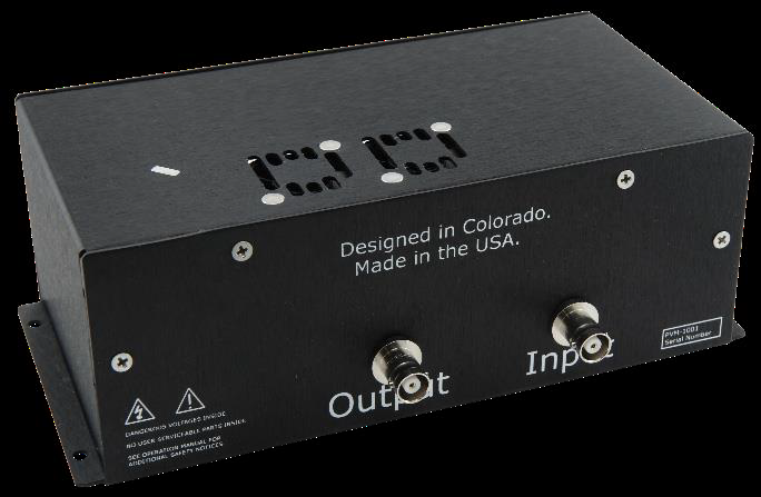
Rear panel
The rear panel carries MHV connectors for the HV input and the pulsed HV output. The HV input takes the external high-voltage DC source (positive for the -P, negative for the -N), and the HV output delivers the switched pulse to the 50 ohm load. Keeping the high-voltage connections on the rear panel separates the operator-facing trigger and power from the live HV path.
5Applications
The PVM-1001 fits work that needs fast, clean, externally timed high-voltage pulses into a 50 ohm load:
- Instrument calibration. Provide a repeatable, sharply defined pulse edge as a reference for high-voltage and timing measurements.
- Component testing. Stress and characterize devices under fast pulsed bias, with pulse width and rate set from your existing trigger source.
- Beam steering. Switch high-voltage potentials quickly for deflection and steering in beam-based instruments.
- PMT and MCP gating. Gate photomultiplier tubes and microchannel plates with sub-10 ns rising edges to capture or reject signal windows precisely.
Across these uses, the external-trigger architecture is the common thread. Because pulse width and frequency follow the trigger, the PVM-1001 slots into a larger timing system rather than dictating its own.
6Ordering Information
Choose the module polarity to match your load and bias scheme, then add the cable set as needed. Both modules share the same speed and burst capability.
| Model | Description |
|---|---|
| PVM-1001-P | Positive module. Produces positive voltage pulses; requires an external positive HV power supply. |
| PVM-1001-N | Negative module. Produces negative voltage pulses; requires an external negative HV power supply. |
| PVA-1001 | Input and output cables. |
Contact
For a quote, configuration help, or application support, reach the Berkeley Nucleonics team.
Email: info@berkeleynucleonics.com
Phone: 800-234-7858