1Overview
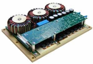
The PCO-6141 is a compact, OEM-style high-power pulsed current source designed to drive diode lasers, bars, and arrays in pulsed, QCW, or CW modes. It delivers output current variable from 1 A to 60 A, pulse widths variable from under 100 ns to DC, and pulse repetition frequencies variable from single-shot to 500 kHz at duty cycles up to 100%.
A user-adjustable variable rise-time control sets the system apart. A PCB-mounted potentiometer adjusts the rise time within a range of under 12 ns to over 1.5 us, so the driver edge can be optimized for the load and the application, rather than fixed at the factory. This makes the module flexible across a wide span of diode types and pulse-shape requirements.
Directed Energy, Inc. is now a division of Berkeley Nucleonics. The PCO-6141 is the same design, built in California, with one support path. Its rugged, compact form and high-power capability make it a strong OEM choice for integration into laser systems and instruments.
2How It Works
The PCO-6141 is based on a hysteretic, average-current, switch-mode regulator. This is a variable-frequency, variable-pulse-width design that maintains current in an energy-storage inductor between a minimum and a maximum level, with ripple limited to the band set by the hysteretic controller. The regulator starts when the TTL enable line goes high and runs as long as enable is held high. The architecture gives a large input range and high efficiency.
A shunting switch shorts the regulator output until output current is needed. The pulse is generated by opening the shunt switch for the length of the input gate pulse. Pulse rise and fall times are then limited only by the stray and parasitic capacitance and inductance of the shunting switch and output leads, which is why the output leads matter and why rise time is adjustable.
No power is dissipated in the driver until it is enabled. When enabled at 60 A maximum output, roughly 80 W is dissipated continuously to maintain current in the storage inductor. At 60 A output the stored energy in the driver is about 7 joules, dramatically lower than comparable linear current sources, which lowers fault energy reaching the diode.
3Output Specifications
Specifications are subject to change without notice.
| Pulse amplitude | Specification |
|---|---|
| Output current range | 0 A to 60 A |
| Means of adjustment | Trimpot mounted on PCB, or external 0–5 V or 0–10 V analog voltage, jumper-selectable |
| Output polarity | Positive |
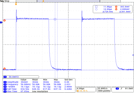
| Pulse rise time | Variable, under 12 ns to over 1.5 us (10% to 90%), user-adjustable PCB trimpot |
| Pulse width | 100 ns with 6 V compliance; 200 ns to DC |
| Pulse frequency range | Single-shot to 500 kHz |
| Maximum duty cycle | 100% |
| Output pulse ripple/droop | Less than 1 A, less than 1.7% at 60 A output |
| Jitter | Less than 3 ns, first sigma |
| Efficiency | Greater than 55% at 50% duty cycle, 60 A output |
| Output connector | High-current DSUB, PCB-mounted |
| Diode forward voltage amplitude | 20 V maximum |
| Gate input & monitor | Specification |
|---|---|
| Gate input type | Positive edge trigger |
| Gate input | +5 V CMOS |
| Current monitor (optional PCA-9150) | 200 A/V terminated into 50 ohm; plus or minus 3% of actual current |
| Current monitor connector | BNC |
| Output enable/disable | TTL input, high = enabled |
4General & Power
| Parameter | Specification |
|---|---|
| Input power | +24 VDC plus or minus 10%, unregulated |
| Operating temperature | 0 C to 40 C |
| Cooling | Air cooled |
| Dimensions (H × W × D) | 5.2 cm × 22.6 cm × 15.9 cm |
5Output Protection & Safety
To protect the laser diode and the driver, circuitry disables the output if the +24 VDC support power drops below 18 V. This undervoltage cutout prevents the regulator from running with insufficient headroom, which is a common path to uncontrolled current.
Clamp diodes are incorporated into the output network to protect the laser diode against reverse-voltage conditions. Combined with the low stored energy of the hysteretic design, roughly 7 joules at 60 A, the module limits the energy that can reach the diode in a fault, which is a meaningful advantage over comparable linear sources.
6Control & Interfaces
The PCO-6141 requires a user-supplied +24 VDC support power input, a CMOS (+5 V) gate signal, and a TTL-level enable/disable signal. The high-current output is derived from the +24 VDC input. Output pulse width and frequency are controlled by the gate signal, and output current amplitude is set by a PCB-mounted potentiometer or, jumper-selectable, by an external 0–5 V or 0–10 V analog voltage.
The optional PCA-9150 current monitor is a 0.01 ohm resistor with a 50 ohm series termination. Terminated into 50 ohm, it presents the equivalent of a 0.005 ohm resistor with scaling of 200 A/V, viewable on an oscilloscope through a BNC connector. The resistor sits in the negative lead, and the BNC shield is connected to the negative output, giving a direct, real-time view of the diode current waveform.
7Applications
The PCO-6141 suits OEM systems that need high pulsed current in a small footprint with a tunable edge.
- Diode lasers, bars, and arrays. Drive high-power emitters and arrays up to 60 A in pulsed, QCW, or CW modes.
- LiDAR and rangefinding. Produce fast current pulses with adjustable rise time and low jitter for time-of-flight systems.
- Materials processing. Supply high-current pulses for marking, micromachining, and illumination at duty cycles up to 100%.
- OEM laser instruments. Embed a compact, high-efficiency, low-stored-energy driver into a larger product.
8Ordering Information
| Part number | Description |
|---|---|
| PCO-6141 | Pulsed/CW Laser Diode Driver Module |
| PCA-9150 | Optional Current Monitor Board (200 A/V into 50 ohm) |
Contact
For a quote, configuration help, or OEM integration support, reach the Berkeley Nucleonics team.
Email: info@berkeleynucleonics.com
Phone: 800-234-7858