February 2017
Introduction
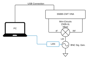
RF mixers are nominally 3-port devices, with IF, RF, and LO connections. When using a 2-port VNA to perform S-parameter measurements of a mixer, an external signal generator is often used to supply the LO input. Legacy systems normally require you to buy their brand for such multi-instrument test systems.
In contrast to legacy test systems which lock the customer into a single-vendor platform, modular, software-centric instruments can now be easily integrated together to form comprehensive test solutions. Incorporation of these devices provides an accurate, easily-configurable test system at an unparalleled price point with a far greater range of hardware options to the user, with a lower cost of ownership that resists obsolescence during its life.
This application note describes a plugin jointly developed by Copper Mountain Technologies and Berkeley Nucleonics to take advantage of each company's' PC-based instruments. The CMT-BNC Mixer Measurement plugin allows for adjusting the LO frequency provided to a Mixer Under Test (MUT) from a BNC signal generator, while a CMT VNA measures this MUT's conversion loss.
Copper Mountain Technologies (CMT) is an Indianapolis, Indiana-based manufacturer of USB Vector Network Analysis modules. Berkeley Nucleonics Corporation (BNC) is a leading manufacturer of precision electronic instrumentation for test, measurement, and nuclear research headquartered in San Rafael, California.
Unlike traditional test and measurement instrumentation, which typically incorporates burdensome industrial PCs and outdated versions of Microsoft Windows, new modular test offerings from CMT and BNC are lightweight, low power, robust, and flexible. One additional benefit of the modular test approach is that applications for both vendors' product families are updated periodically to incorporate new features and to address issues, without the hassle of dealing with outdated, embedded computers.
Instrument Details
BNC Signal Generator
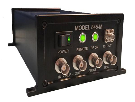
Model 845-20 from Berkeley Nucleonics Corporation is a microwave signal generator with a frequency range of 100 kHz to 20.5 GHz and adjustable power output from -30 dBm to 15 dBm. Across this frequency range, resolution of 0.001 Hz and power output resolution of 0.01 dBm is available to the user. Output phase can also be adjusted from 0° to 360° with a resolution of 0.1°. The accuracy of the BNC signal generator's internal oscillator is ±40 ppb initially, which corresponds to an accuracy of ±40 Hz at 1 GHz generated frequency. The Model 845-20 also exhibits very fast switching between frequency points, 7.2 µs for a 2 GHz increase. These parameters could fit a wide range of use cases, without mentioning the modulation capabilities of this source, and will be more than adequate for our mixer measuring application.
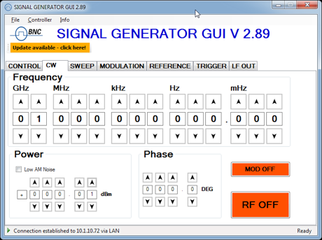
Similar to CMT VNA offerings, the main UI of Model 845-20 is a program that runs on a connected PC. There are several protocols by which users may connect the UI and signal generator including GPIB, USBTMC, and Ethernet LAN. To utilize the BNC signal generator in CMT's Mixer Measurement plugin, SCPI commands were sent over a USB connection utilizing the VISA I/O API.
CMT VNA
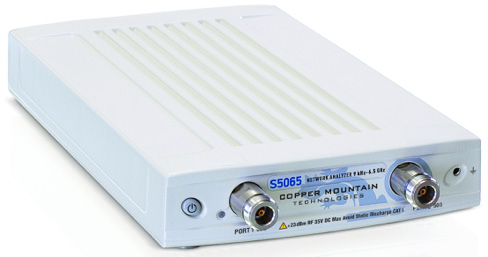
Copper Mountain Technologies' S5065 compact VNA was chosen for mixer measurements because it contains two test sets, and thus can obtain all four complex S-parameters for a two-port network (RF to IF). The frequency range of the instrument spans 9 kHz to 6.5 GHz, with a maximum of 5 dBm power output to a minimum of -55 dBm across the entire frequency range. This frequency and power range combined with frequency offset mode makes the S5065 suitable for characterizing the ZX05-1L. A dynamic range of 130 dB (typical with 1 Hz IFBW) ensures that users can expect accuracy in their measurements. Up to 200,001 frequency points can be measured in any user selected frequency range with an IFBW selectable range between 1 Hz and 100 kHz. This wide range of options is complemented by CMT's VNA software suites, which replace cumbersome onboard computers. Time domain gating and embedding and de-embedding of .s2p characterized devices, among other features, come standard in S5065 VNA.
CMT VNAs support DCOM/COM, and SCPI over TCP/IP, automation interfaces. Instruments connect to a local PC running a CMT software suite, while DCOM and SCPI over TCP/IP functionality allows users to send commands over a network to this locally attached PC. The only local PC requirement is to be capable of running a Windows OS, otherwise a Linux or Mac OS machine can send automation commands to this smaller, Windows machine.
To facilitate user automation of CMT devices many programming examples are made available through the CMT website. Some are downloaded as documentation along with software suite installers. These examples include programs in Python, MATLAB, Excel, C++, VB.NET, and LabVIEW.
Mini-circuits mixer
The MUT chosen for testing the Mixer Measurement plugin was a Mini-Circuits ZX05-1L. With input frequency ranges from 2 MHz to 500 MHz this mixer is designed to produce heterodynes up to 500 MHz; and as a Level 3 mixer, it's LO input is intended to be driven at 3 dBm. Packaged in a small cube, this mixer was fabricated with three SMA inputs and typically exhibits 6 dB conversion loss between RF input and IF output.

Mixer Measurement Plugin
Installing and configuring the plugin
The "CMT-BNC Mixer Meas" plugin is compatible with S2VNA.exe, the Windows app for all 2-port 2-path VNAs from Copper Mountain Technologies. The plugin can be launched from directly inside the S2VNA application via the menu sequence System > Plugins. To install the plugin, simply copy its executable into the /Plugins/ subfolder of your S2VNA installation path (C:\VNA\S2VNA\Plugins by default).
It is also important that the S2VNA application's COM server interface be registered when it is installed in Windows. Either simply check the box for "Register COM Server" during the installer wizard, or run "S2VNA.exe -regserver" at a command prompt after installation.
Using the plugin
Using the CMT-BNC plugin is very simple. Specify the VISA address of the BNC signal generator and the list of frequencies through which the LO should be stepped. Optionally, you can also specify one or more SCPI commands to be sent at the start of measurements, as well as a Pause time to wait after each LO step command.
When "Run" is clicked in the plugin, it will (optionally) execute the signal generator initialization commands you've specified, then command the signal generator to the first frequency, and (optionally) wait the specified time. Then a single trigger will be issued on Channel 1, which starts the VNA sweep.
At the end of the sweep, the signal generator is stepped to the second frequency in the list, and so on. When the end of the frequency list is reached, the signal generator returns to the start frequency and trigger control is restored to its original settings.
Test Results
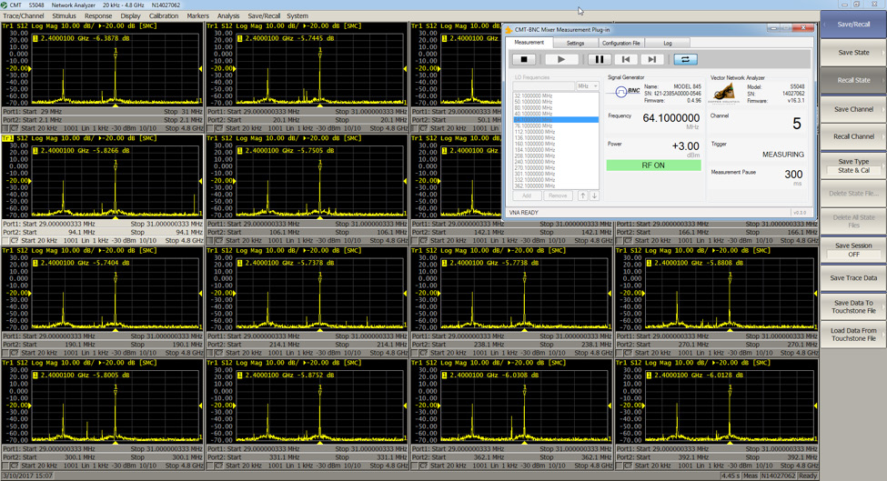
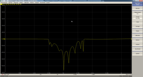
In preparation for the measurement of the conversion loss as a function of input frequencies, a scalar mixer calibration was performed on the S5065. Frequency offset was also turned on under the "Stimulus" menu to ensure Port 1 of the VNA was always receiving in the 29-31 MHz band. Port 2 of the instrument was designated the RF input to the mixer, and the BNC signal generator was designated as the LO input; then a series of upconversion and downconversion frequencies were selected corresponding to the ZX05-1L MUT data sheet. Regardless of whether upconversion or downconversion was occurring, the chosen IF was a constant 30 MHz. Once given a list of LO frequencies the Mixer Measurement plugin mirrors Channel 1 sixteen times; with the exception of frequency offset on Port 2, which was altered based on the LO frequency of that index in the list. Each LO, RF frequency combination was repeated and averaged ten times. The IFBW was selected wide enough such that the measurement frequency point closest to the 30 MHz IF of the MUT would detect the power of the 30 MHz IF. An intermodulation product can be seen just below 29.4 MHz in each channel.
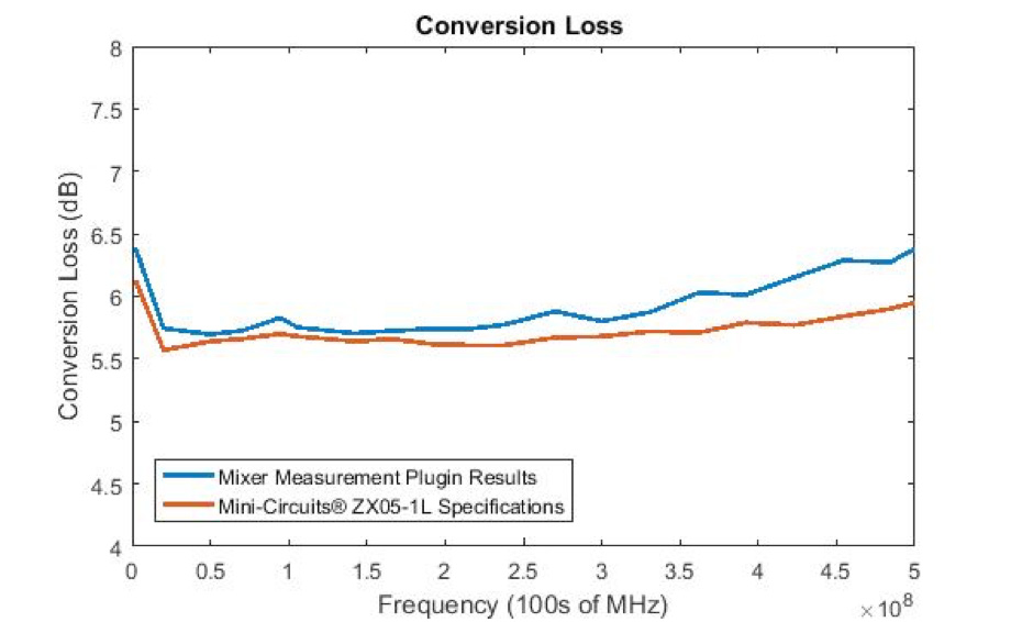
The above plot was produced using MATLAB. On average, the conversion loss recorded was 0.2 dB higher than specified in the ZX05-1L's data sheet.
Conclusion
Alone, both brands provide significant advantages in usability and compatibility over legacy instrumentation. Without the additional hassle of onboard computers, CMT end users can extract data immediately to directories pertinent to additional processing. The Signal Generator GUI reduces the hassle of using clunky buttons to switch frequency and power of stimulus signals. BNC's Signal Generator GUI and CMT's software suites both reduce the time and effort required to update device firmware. By pre-selecting frequencies of interest and automating coordination of the test and stimulus setup, MUT conversion loss data was collected rapidly and accurately; together these USB devices make a powerful combination for increasing measurement throughput. Making the setup ideal for production environments. Refusing to lock our customers into a particular brand enables end-users to design custom solutions to their needs at unbeatable price points. If you have any questions about automating test setups using CMT products, please contact support@coppermountaintech.com. Likewise, questions about automating BNC products may be directed to rfsupport@
| Berkeley Nucleonics Corporation | Copper Mountain Technologies |
|---|---|
| berkeleynucleonics.com | coppermountaintech.com |
| US Office: +1.800.234.7858 | US Office: +1.317.222.5400 |
| Singapore Office: +65.63.23.6546 |