This application note describes how to program the model series 855 instruments featuring multiple output channels.
The basic multi-channel programming command syntax is introduced. An example shows how to configure multiple channels individually.
Introduction
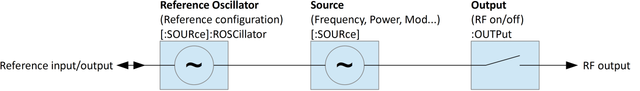
Devices with only one single channel provide one source and one output programming node. The [:SOURce]:… and :OUTPut:… ranges of command enable remote programming of reference configuration, source setup (frequency, power, modulations etc.) and output state (RF on/off).
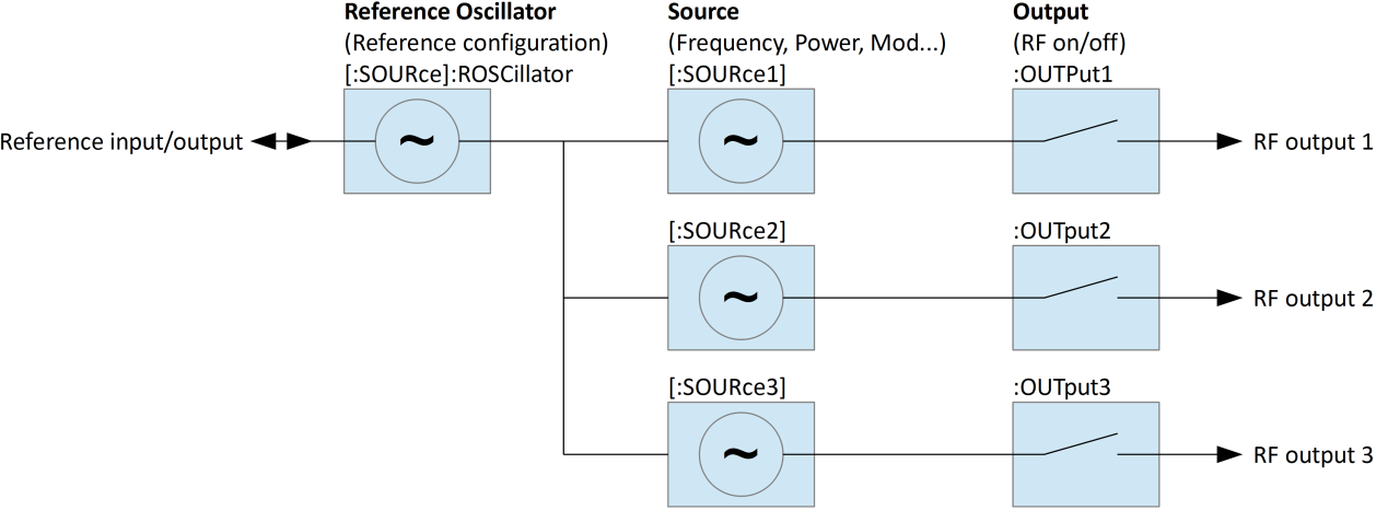
Multi-channel devices provide multiple [:SOURce]:… and :OUTPut:… programming nodes, each of it dedicated to one of the channels. However, some sub-nodes are common to all channels. For example, frequency, power and modulations can be set per channel while the reference part is common to all channels.
Channel Selection
The channel can be selected in two different ways.
- Append a channel index to the [:SOURce] and :OUTPut nodes: [:SOURce#] and [:OUTPut#], e.g. :SOURce1.
- Select the default source and output nodes. Commands within the [:SOURce] or OUTPut nodes will apply to a selected default source if no channel index is appended.
Individual and Shared Settings
Some [:SOURce] and :OUTPut sub-nodes are common to all channels. Programming such sub-nodes will affect all channels at once. Channel index and default source selection won’t have any effect. This applies to the following sub-nodes:
| Sub-node | Description |
|---|---|
| [:SOURce]:ROSCillator | Reference configuration. Common for all sources. |
| [:SOURce]:SELect | Default source selection. |
Quick Command Reference
This quick command reference covers basic multi-channel functionality: reference configuration, channel selection, per-channel frequency, power and output state settings. Please refer to the signal generator programmer’s manual for a complete command reference.
[:SOURce]:SEL?
[:SOURce]:SEL? MINimum
[:SOURce]:SEL? MAXimum
[:SOURce]:SEL <x>
Gets or sets default source and output channel selection. Range 1…number of channels. The MAXimum query returns the number of sources available. Reset (*RST) default: 1.
[:SOURce#]:FREQuency?
[:SOURce#]:FREQuency <x>
Gets or sets source frequency. Applies to currently selected default source if [:SOURce#] node or source index # is omitted. Applies to source # (range 1…number of channels) otherwise.
[:SOURce#]:POWer?
[:SOURce#]:POWer <x>
Gets or sets source power. Applies to currently selected default source if [:SOURce#] node or source index # is omitted. Applies to source # (range 1…number of channels) otherwise.
[:SOURce]:ROSCillator:SOURce?
[:SOURce]:ROSCillator:SOURce INTernal|EXTernal
Gets or sets reference source. Applies to all channels. Reset (*RST) default: INTernal.
[:SOURce]:ROSCillator:OUTPut[:STATe]?
[:SOURce]:ROSCillator:OUTPut[:STATe] 0|1|OFF|ON
Gets or sets reference output state. Reset (*RST) default: 0|OFF.
:OUTPut#[:STATe]?
:OUTPut#[:STATe] 0|1|OFF|ON
Gets or sets output state. Applies to currently selected default output if the output index # is omitted. Applies to output # (range 1…number of sources) otherwise. Reset (*RST) default: 0|OFF.
Programming Examples
Programming of the following setup:
- Reference source external, reference output enabled
- Source 1: 0 dBm, 1 GHz, output enabled
- Source 2: 5 dBm, 2 GHz, output enabled
- Source 3: 6 dBm, 2.1 GHz, output enabled
Method A: Specifying source and output indices
ROSC:SOUR EXT
ROSC:OUTP ON
SOUR1:POW 0 DBM
SOUR1:FREQ 1 GHZ
OUTP1 ON
SOUR2:POW 5 DBM
SOUR2:FREQ 2 GHZ
OUTP2 ON
SOUR3:POW 6 DBM
SOUR3:FREQ 2.1 GHZ
OUTP3 ON
Method B: Changing the default source selection
SOUR:SEL 1
POW 0 DBM
FREQ 1 GHZ
OUTP ON
SOUR:SEL 2
POW 5 DBM
FREQ 2 GHZ
OUTP ON
SOUR:SEL 3
POW 6 DBM
FREQ 2.1 GHZ
OUTP ON