During the testing of the Model 805-SG by BAE, they have come across a behavior which is problematic for their application. When stepping the power by 0.10 dB, the measured power change of the 805-SG sometimes has an error of more than 0.05 dB (their expectation). While Anapico has no hard specification on this metric and thus the unit is not out of specification, BAE expects an improvement of the performance. This document analyzes the current performance and gives methods to possibly improve it.
1. Test setup for this document
The measurements in this document were done on the APMQS 9D0-012000000-0352. The power sensor used is the Ladybug LB5940L 209594.
The BAE unit was calibrated with the base settings: APMQS-SYN_APMQS20_OUT_1B-8K
The Test Unit for this document was calibrated with the base settings: APMQS20-SYN_APMQS20_OUT_1B-No_Detector_Attenuation-8k
The measurements were made in the same manner as described by BAE in their power point document “BNC Unit Testing DDA-012000000-0338 Power Step Testing.ppt”:
| Parameter | Values |
|---|---|
| Tested Frequencies | 200 MHz, 1 GHz, 1.75 GHz, 2.5 GHz, 3.75 GHz, 6 GHz, 10.5 GHz, and 15 GHz |
| Tested Powers | -10 dBm to +13 dBm in 0.1 dB steps |
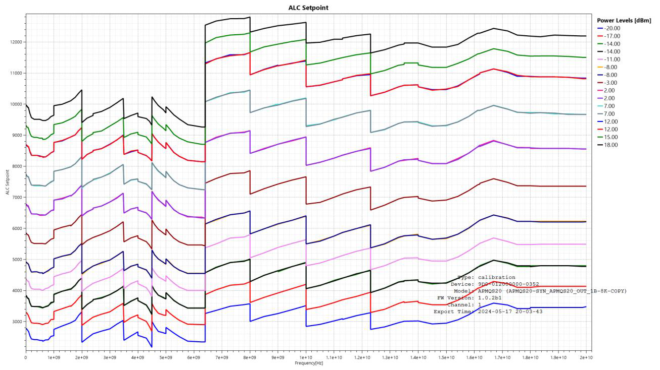
2. Current BAE setup
The BAE measurements show step inaccuracies of typically 0.05 to 0.08 dB. However, at power levels -8 dBm, 2 dBm, 12 dBm, the step inaccuracies are typically 0.15 to 0.20 dB.
Explanation
- -14, -8, 2, 7, 12 are power zone limits. At these power levels, depending on the frequency band, gain stages are switched in.
- At power zone limits, the attenuation level of the attenuator in front of the power detector is modified. This is meant to keep the power levels at the detector input within a certain window.
- The power levels within a power zone are related to each other, while power levels between different power zones are unrelated.
Measurements made on our test unit in the same conditions as the BAE unit:
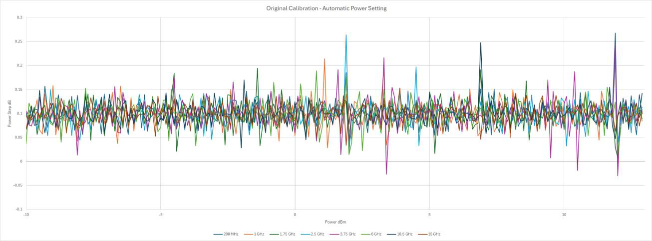
The results are similar to those of BAE.
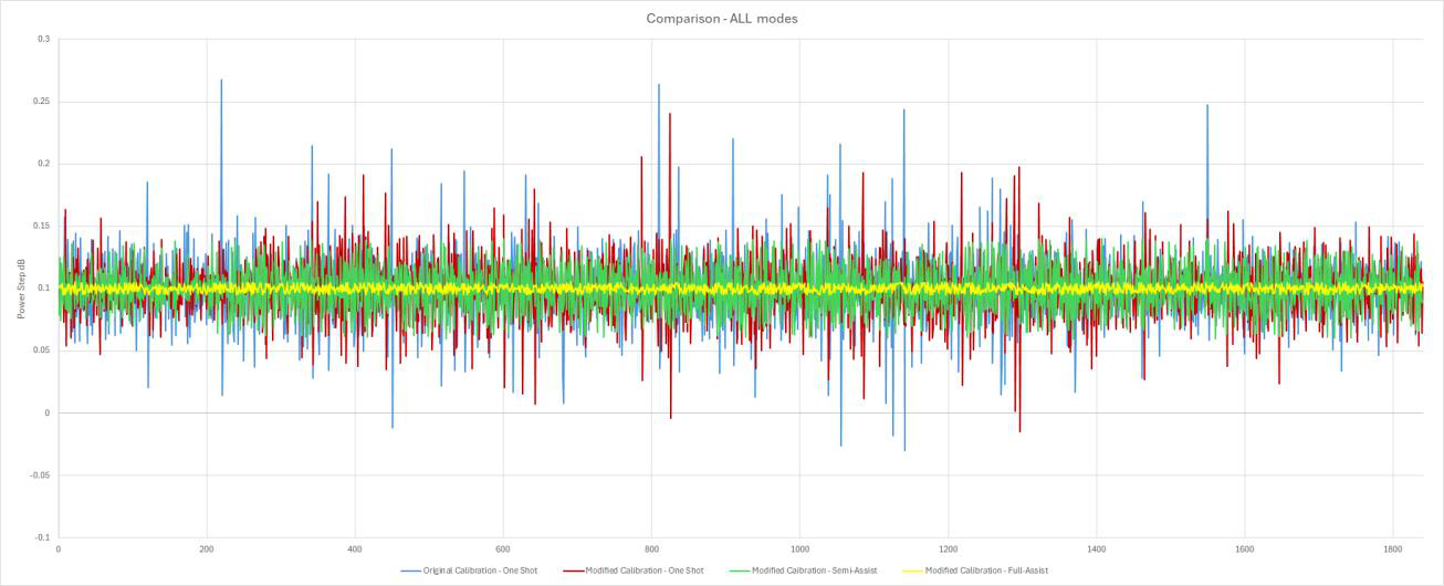
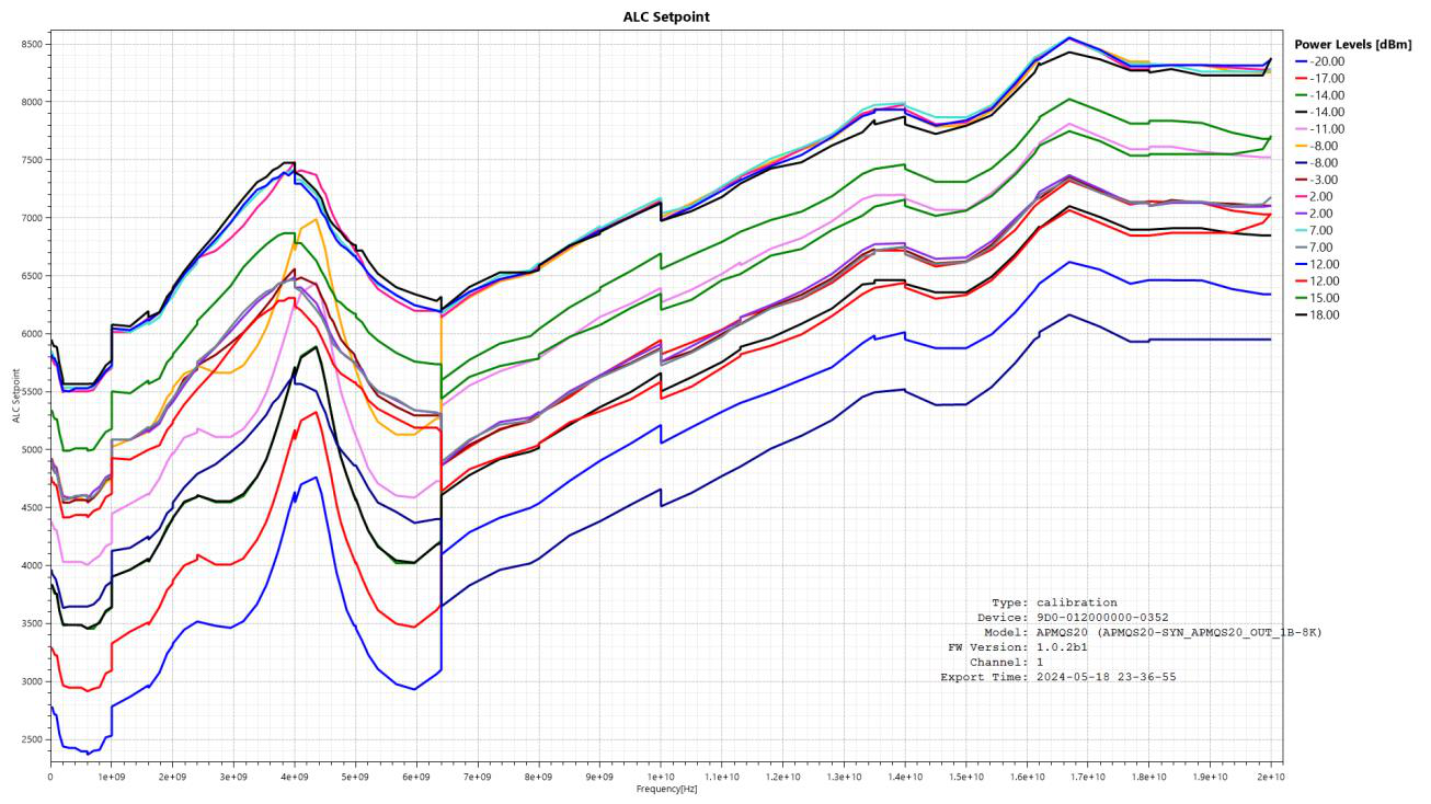
3. Modified Calibration Method — the detector attenuator is set to the same value for all power zones
We modified the calibration settings so that the attenuation level of the power detector attenuator is the same in all power zones. Furthermore, after calibration, we manually set the set points of the lowest power level of a power zone to be equal to the setpoint of the highest power level of the lower power zone.
a) Fully automated power setting
For these measurements, the power is stepped through in 0.1 dB step. The power setting is left to the firmware, one shot ALC.
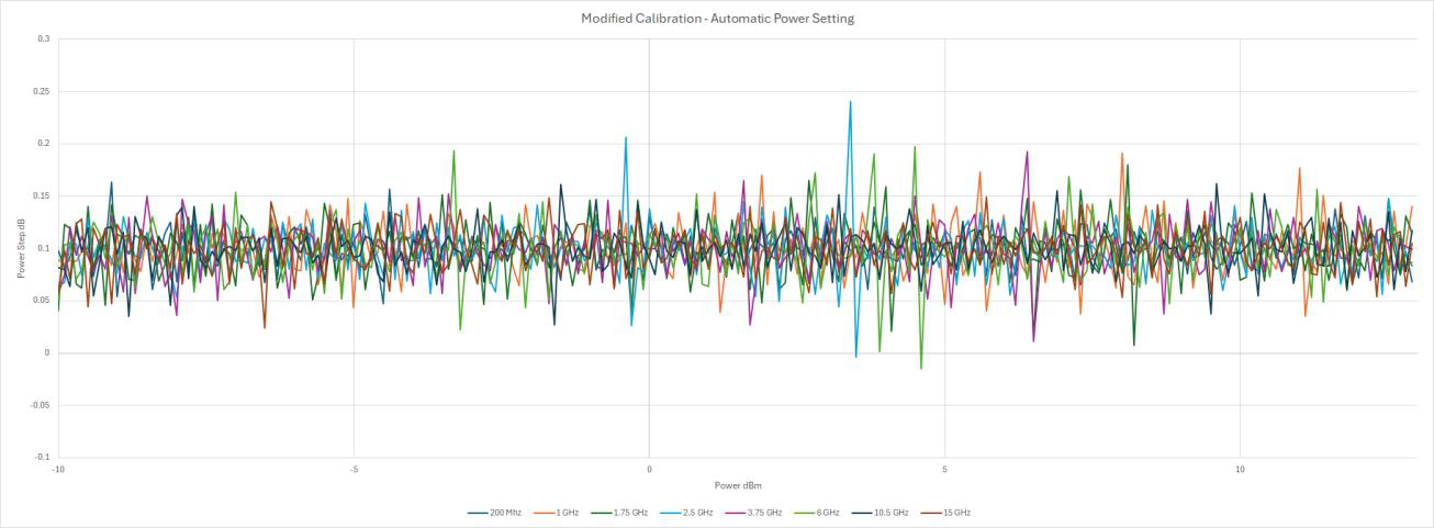
Modified the Calibration allows to eliminate the inaccuracies at power zone limits. However, the “one shot” Automatic Level Control does not ensure a power step accuracy of 0.05 dB for a 0.1 dB step.
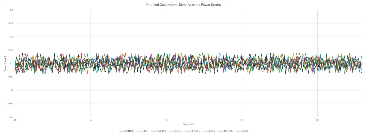
b) Software simulated Closed ALC loop (Semi-Assisted mode)
The “one shot” ALC not offering accurate enough results, we simulated a closed ALC Loop in our testing software: To do so, the power command is sent until the step accuracy is within the allowed 0.05 dB (maximum 50 attempts).
The power accuracy was reached on average after 1.2 attempts. The highest number of attempts was 27.
c) Software Full-Assist of power setting
The Semi-assisted power setting mode shows that the expected power step accuracy can be easily reached by sending the power command several times until the output power is within the allowed window. It also shows that the APMQS / Model 805-SG internal power detector’s accuracy is limited.
As a final test we tried a “Fully-Assisted” power setting mode. In this mode, instead of letting the internal ALC handle the power setting, we bypassed the level control by directly working with the Control Value.
To achieve the results shown below, the power setting is done as follows:
- Set power to target power + 0.3 dB.
- Use Semi-Assisted power setting until measured output power > target power.
- Binary search of ideal Control Value until target power error < 0.005 dB.
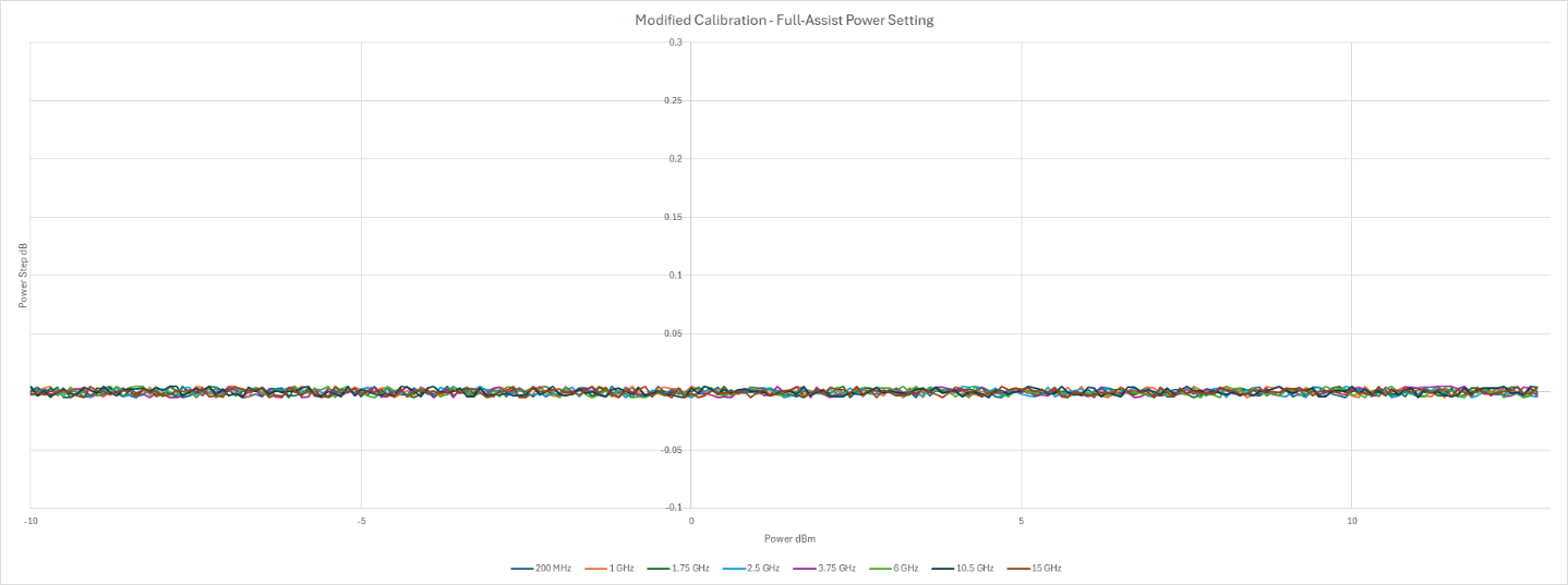
In this attempt, each power setting took about 2 seconds. It should however be possible to optimize the setting time.
d) Conclusion
While it is possible to eliminate the power inaccuracies at the power zone limits by modifying the calibration settings, the overall accuracy of the FW level setting is not good enough to reach the expected specification of < 0.05 dB error for a power step of 0.1 dB. Modifying the ALC to a closed loop in the FW could possibly improve the accuracy.
However, we have shown that the target is achievable by simply sending the power command 1.2 times on average (Semi-assisted mode) and even achieve an accuracy of < 0.005 dB (Fully-assisted mode).
Using the Semi-Assisted or Fully-Assisted modes depend on BAE’s capacity to take power level measurements during their operation.
The Fully-Assisted mode could be turned into a “one-shot” level setting by building a lookup table but would require best temperature stability.