Industry
Berkeley Nucleonics' products are used by some of the most demanding and prestigious organizations:
- Boeing
- NASA
- Hughes
- Jet Propulsion Laboratory
- Intel
- SLAC
- Raytheon
- Sandia National Laboratory
- Lockheed-Martin
- Los Alamos National Laboratories
Universities
- MIT
- Princeton University
- Harvard University
- Stanford University
- Cornell University
Pulse and Digital Delay Generator
Applications and Technology
Industry and Product History
- With technology advancements and experimental demands, the requirements for triggering, syncing, delaying, and gating events grew and the Digital Delay Generator was produced.
- Typically, DDG timing resolution is much finer and the delay and width jitter much less than pulse generators.
- Historically, digital delay generators were single channel devices with delay only.
- Today, technology offers advanced programming capabilities, and a variety of signals and outputs (electrical and fiber).
- Digital delay generators are usually the heart of the timing for larger systems and experiments.
Typical Applications
- Imaging
- PIV
- Particle Sizing
- Laser Imaging
- High Speed Cameras
- Spray Patternation, combustion research
- Flow Visualization
- High-speed Imaging
- RADAR simulation
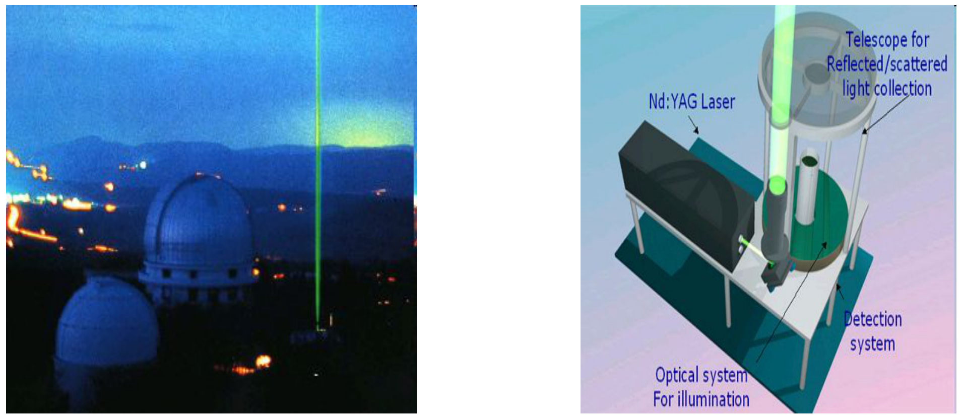
- LIDAR (Laser Imaging Detection and Ranging)
- Atmospheric physics and research
- Meteorology, topographic survey
- Oceanography, estimation of general biomass in the surface layers of the ocean
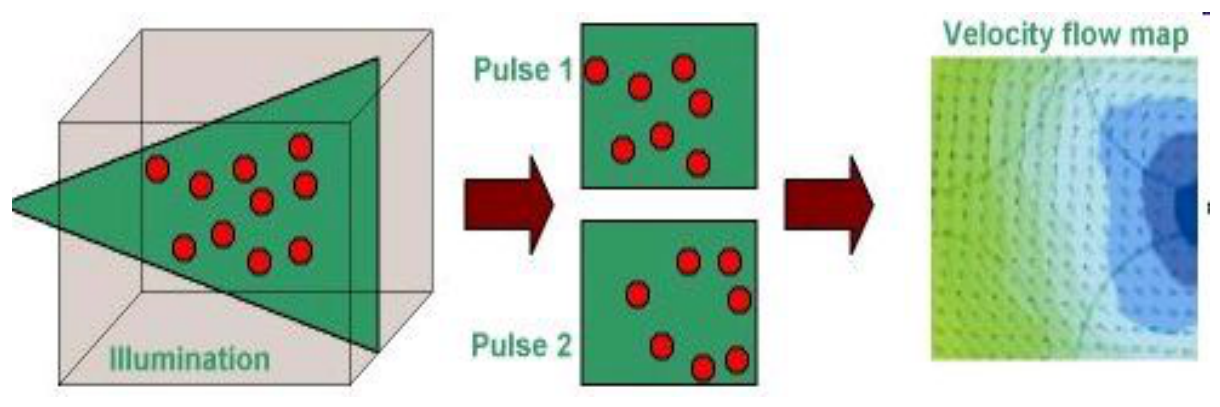
PIV
PIV is an application used widely in the field of fluid dynamics. It enables complex flow patterns to be studied in both liquids and gases.
Firstly the flow medium is seeded with particles. This is then illuminated with two light-sheets generated by a pair of pulsed Nd:YAG lasers (such as the Quantel Brilliant Twins). By using a pair of lasers the time interval, Dt, between pulses is precisely controlled. A CCD camera mounted at right angles to the light sheet records the positions of the particles at the first pulse in one frame and the subsequent particle positions at the second pulse in the second frame. Analysis of these two images enables a velocity flow map to be constructed as represented below:
LIDAR
Typical Applications
- Fluid Dynamics
- Q-switch
- Pulse Power
- Flash X-ray
- High energy discharge
- Laser triggering/synchronization
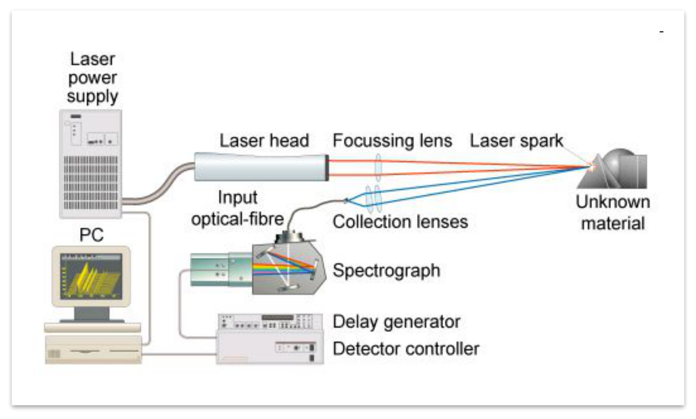
- LIBS (Laser-Induced Breakdown Spectroscopy)
Timing is a variable in every LIBS application and proper synchronization between the laser and detector and ICCD can greatly enhance the efficacy of a system.
LIBS
Pulse and Digital Delay Generator
Features Overview
Instrument Features
- System Modes
- Independent Channel Modes
- System Gating
- Channel Gating
- External Trigger
- Channel Multiplexing
- TTL/Adjustable Modes (9600 adj only)
- Negative Delays
- Channel Sync Source
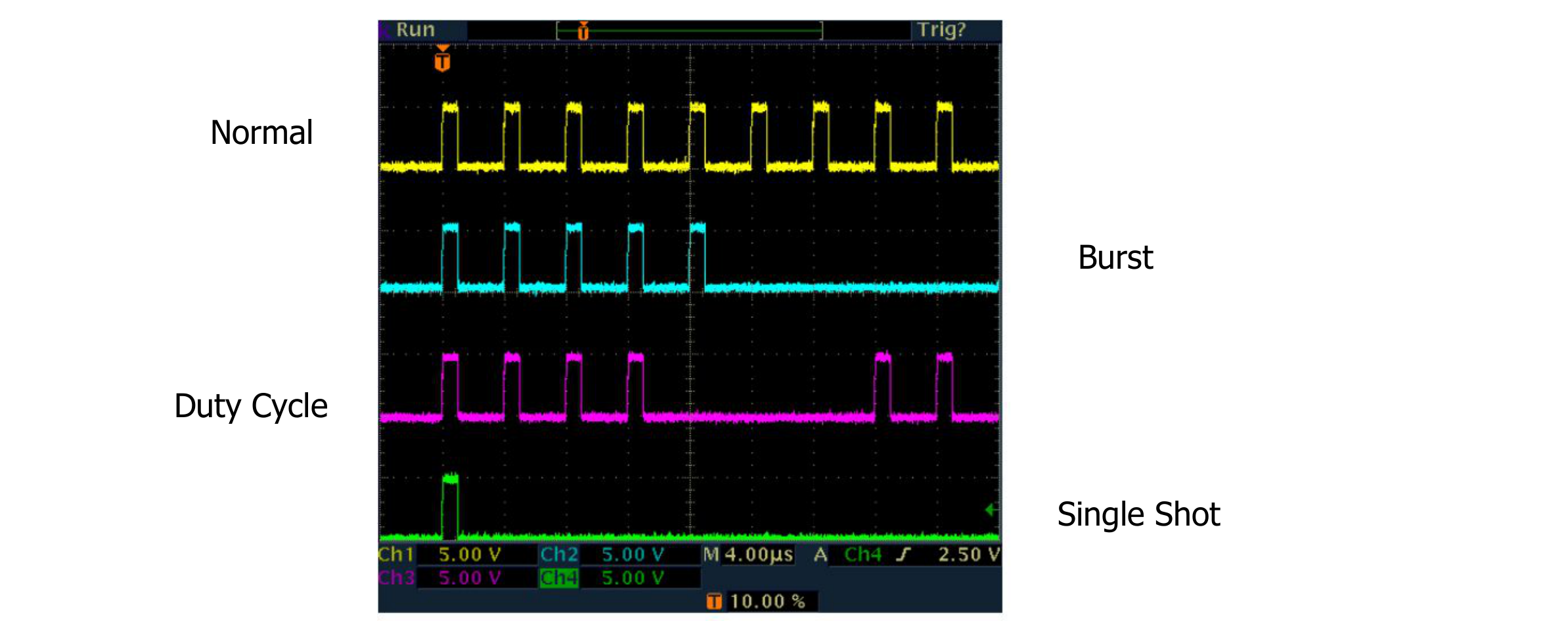
System Modes
- Continuous: Pulses start at a specified rate once a trigger signal or the run/stop button is pressed.
- Burst: A specified number of pulses at a specific rate is output with every trigger or run/stop button press.
- Duty Cycle: A number of on pulse cycles followed by a number of off pulse cycles is started with a trigger or the run/stop button.
- Single Shot: One pulse out for every trigger signal or run/stop button press.
Independent Channel Modes
- All the same modes as the system but on a per channel basis.
- The “normal” channel mode mimics the system mode without any additional setup.
- The output follows the system or channel mode; whichever is more restrictive.
Gating and Trigger
- There are two forms of gating: system and channel.
- System gating affects all channels.
- Channel gating is specific to each individual channel.
- System gating and channel gating can not be operating at the same time.
- Trigger currently operates on a system level.
Channel Multiplexing
- Channel multiplexing allows for the combination of any or all channel settings or all channel signals through any or all physical outputs.
- Channel multiplexing only combines timing events of the channels and not the actual output voltages.
TTL/Adjustable, Negative Delays, Sync Source
- Standard TTL and Adjustable voltage outputs are available.
- Adjustable voltage up to 20V DC.
- Negative delay settings allow for one channel initiating prior to the synchronized source channel.
- Synchronize the timing of one channel to the timing events of another channel.
Instrument Features (continued)
- Selectable Clock-in
- Selectable Clock-out
- Saved Settings on Power Down
- Illuminated Run/Stop Button
- New features can be added to instruments, via a software uploader, without the need to send the unit back to the factory.
- Clock-in/Clock-out is now a standard feature.
- Clock-in can now accept up to a 100 MHz external frequency/master clock.
- System phase-locks to clock source and all timing becomes relative to that signal with very low jitter (50ps).
- Clock-out offers a number of frequencies and the To frequency.
- Internal clock jitter <50 ps.
- External trigger jitter has been significantly decreased over the previous pulse generator.
- Jitter is specified as being <800ps RMS.
- Worst case jitter is 2.5ns.
- Improved Clock-in/Clock-out feature.
- Lower voltage input: down to 20mV.
- Ability to select clock-in frequency in steps of 1MHz from 10MHz to 100MHz.
- Output signal from Clock-out to help in oscillator threshold selection.
575/577 Series Pulse Generator
Features Overview
Current & Existing Features
- System Modes
- Independent Channel Modes
- System Gating
- Channel Gating
- External Trigger
- Channel Multiplexing
- TTL/Adjustable Modes
- Negative Delays
- Channel Sync Source
Existing Features: System Modes
- Continuous: Pulses start at a specified rate once a trigger signal or the run/stop button is pressed.
- Burst: A specified number of pulses at a specific rate is output with every trigger or run/stop button press.
- Duty Cycle: A number of on pulse cycles followed by a number of off pulse cycles is started with a trigger or the run/stop button.
- Single Shot: One pulse out for every trigger signal or run/stop button press.
Independent Channel Modes
- All the same modes as the system but on a per channel basis.
- The “normal” channel mode mimics the system mode without any additional setup.
- The output follows the system or channel mode; whichever is more restrictive.
Compilation of Some Available Modes
575/577 Key Features
- 250ps timing resolution with <50ps jitter.
- 8 independent outputs with full individual programming and control.
- Internal rate generator with 5ns period resolution over entire frequency range (20MHz).
- Complete channel and system setup stored in memory, providing 14 memory storage slots.
- Remote programmability via RS232, USB and Ethernet.
- Dual inputs (gate and/or trigger).
575/577 Key Features: Channel Properties, Advanced Programming Modes
- Multiplexing: Selectively combine the timing of any or all channels to one output.
- Burst: Each channel can have a separate number.
- Duty Cycle: N pulses on, M pulses off.
- Channel Referencing: Any or all channels can reference the timing of any channel rather than T0, rising or falling edge, with either positive or negative reference.
- Wait: The system will wait for a specified number of cycles before producing a pulse.
575/577 Advanced Features/Options
- Clock input/output: allows master clock input from 10MHz to 100MHz with complete system timing relative to that signal with low jitter.
- Field programmability: custom features, upgrades, and fixes via fully programmable FPGA.
- Settings / Programming saved on power down.
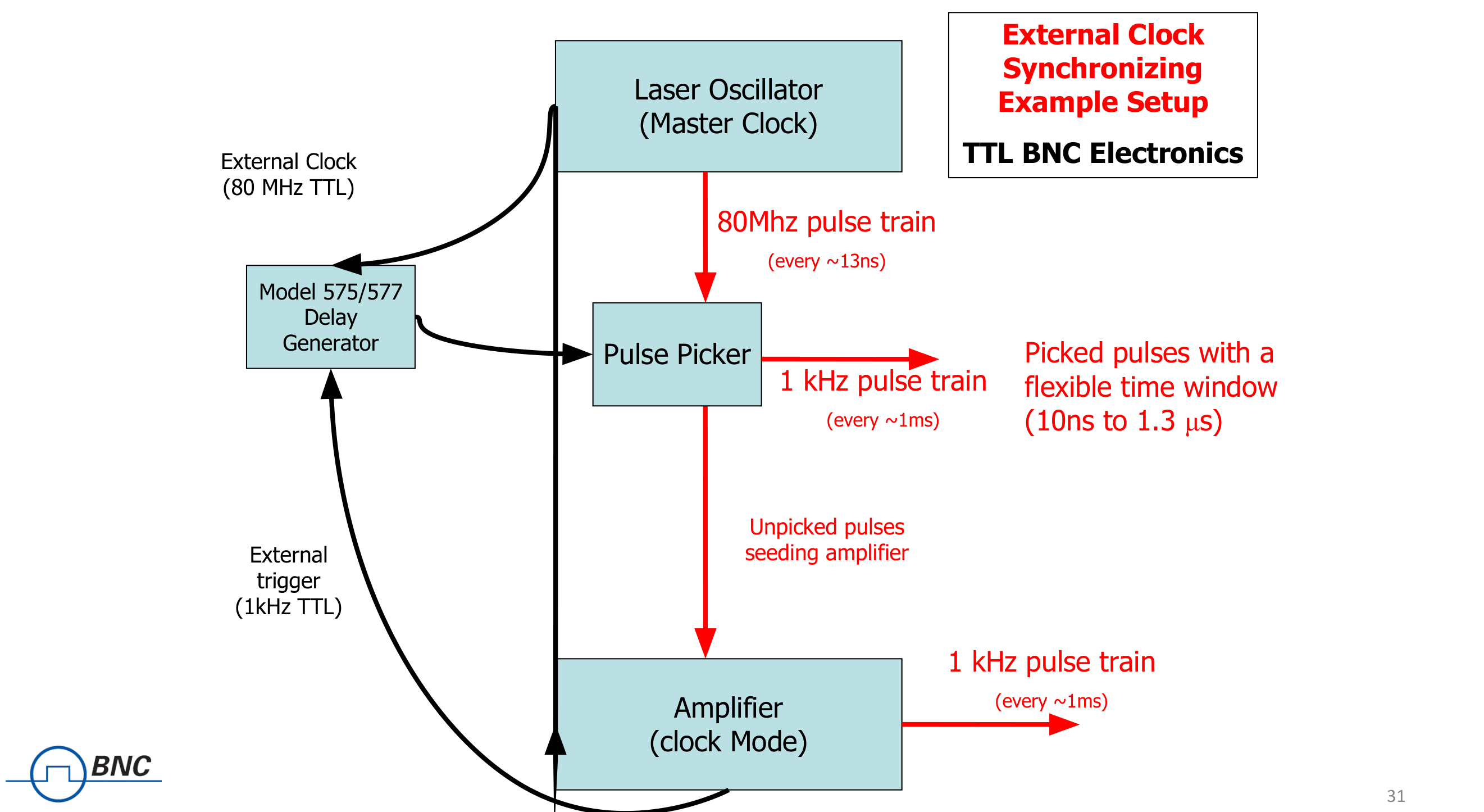
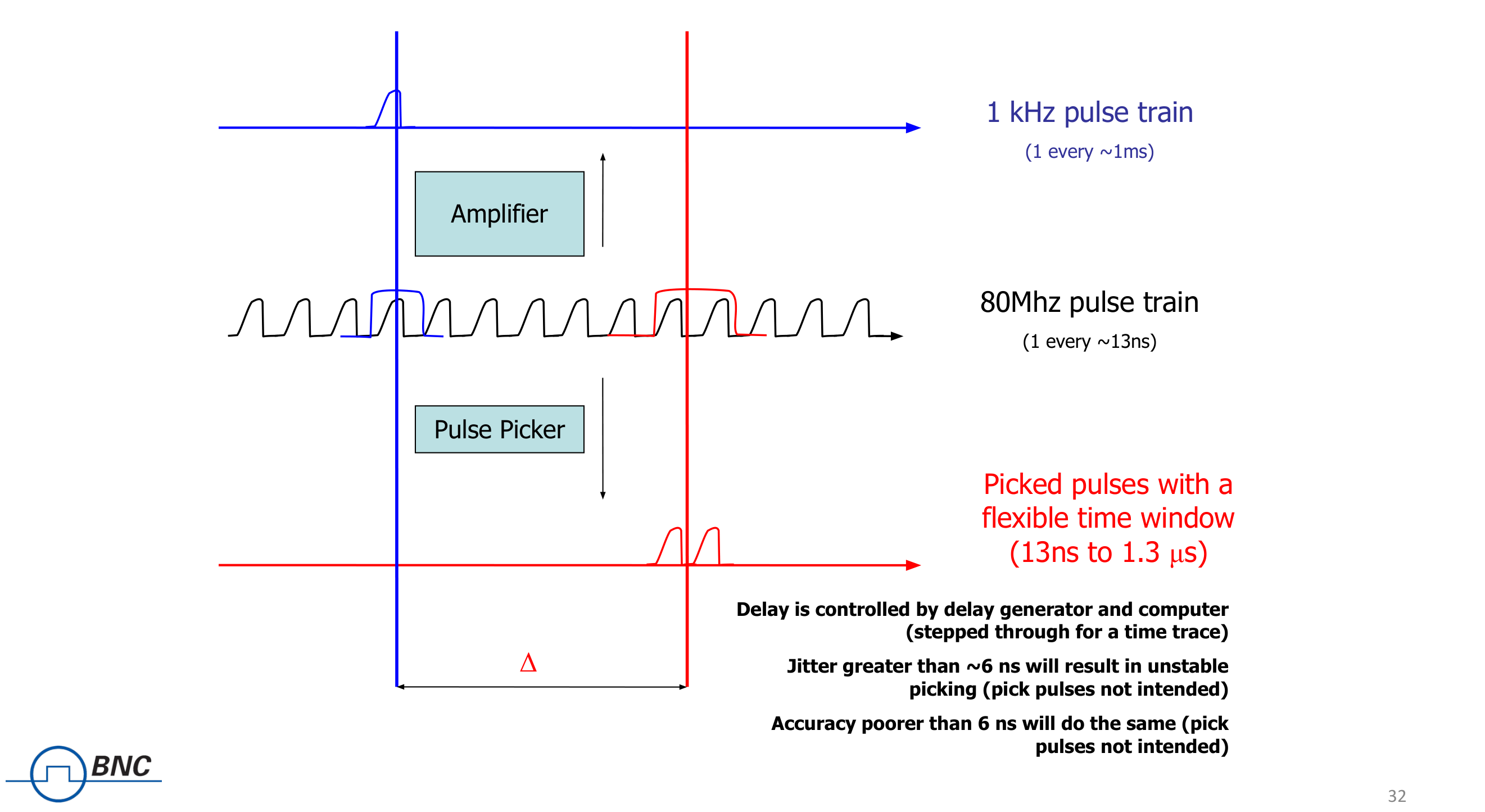
External Clock Synchronizing Example Setup
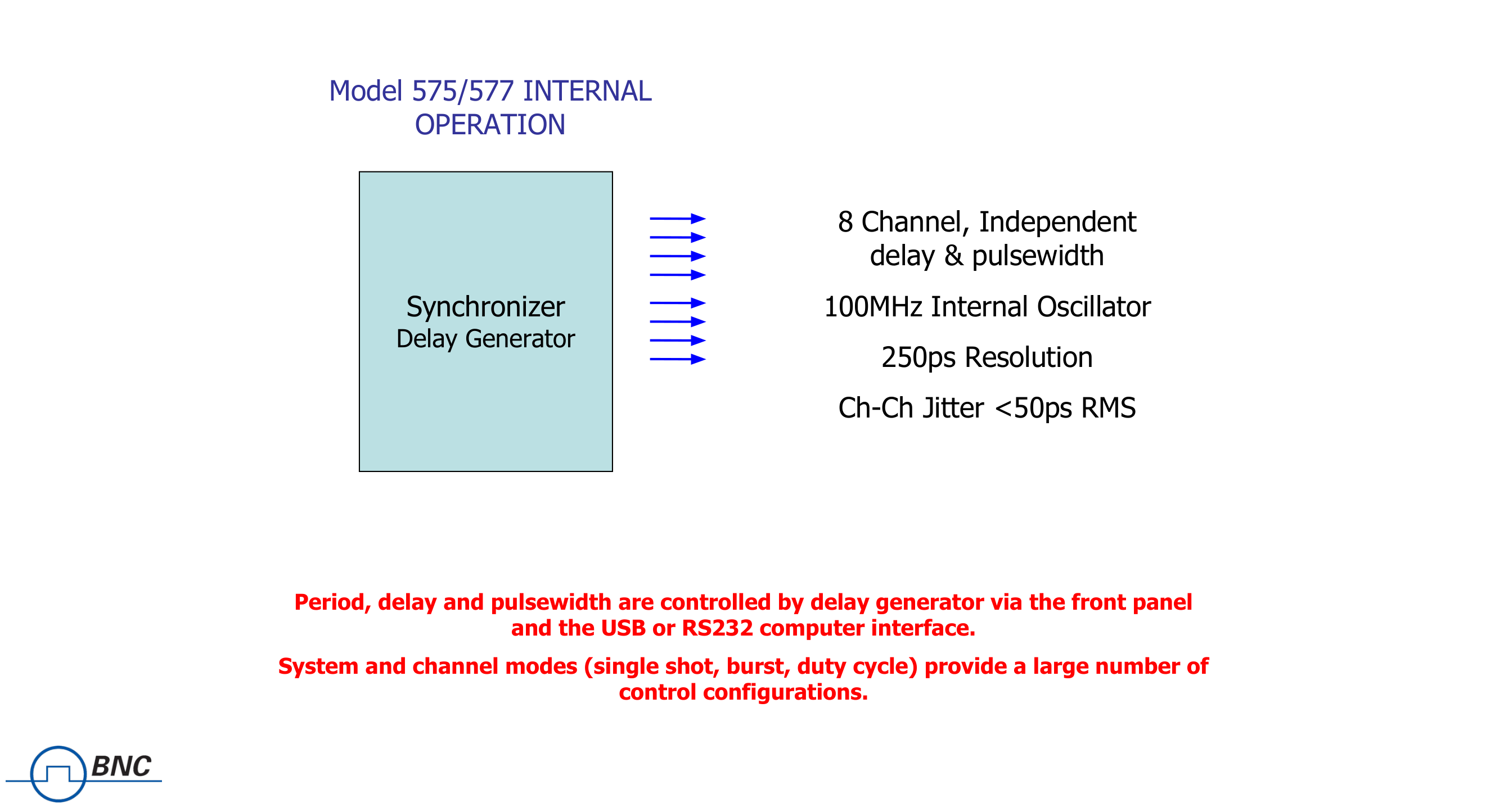
Model 575/577 Internal Operation
Period, delay and pulsewidth are controlled by the delay generator via the front panel and the USB or RS232 computer interface. System and channel modes (single shot, burst, duty cycle) provide a large number of control configurations.
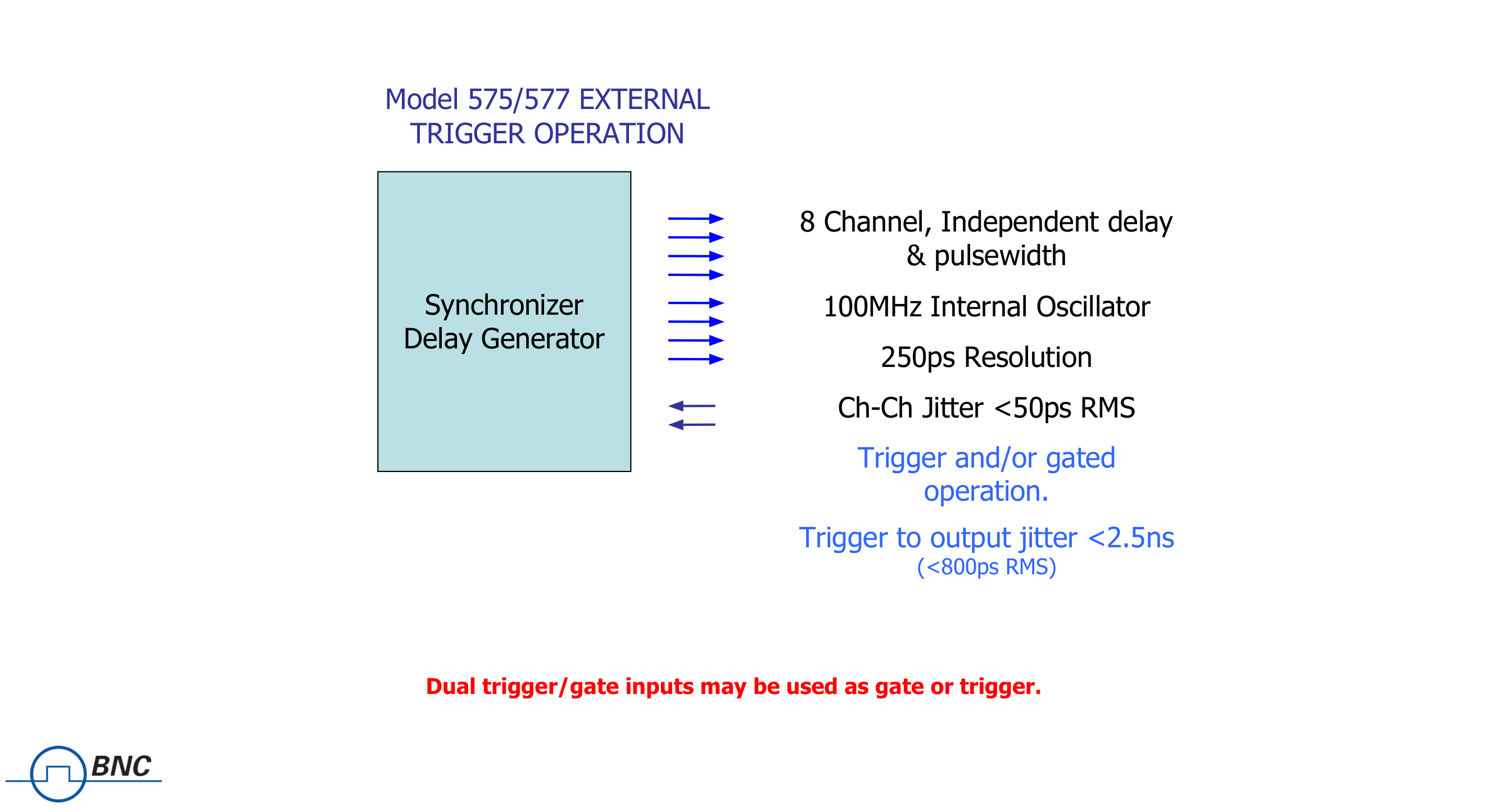
Model 575/577 External Trigger Operation
Dual trigger/gate inputs may be used as gate or trigger.
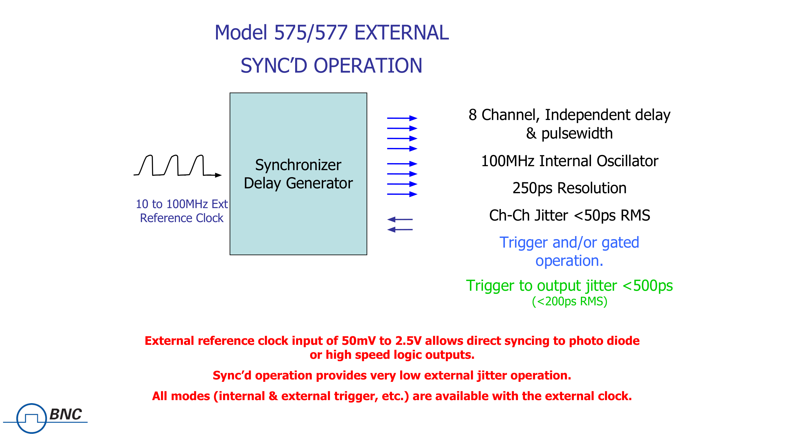
Model 575/577 External Sync'd Operation
External reference clock input of 50mV to 2.5V allows direct syncing to a photo diode or high speed logic outputs. Sync'd operation provides very low external jitter operation. All modes (internal & external trigger, etc.) are available with the external clock.
Model 575/577 Channel Modes Applications
- Independent Channel Enable/Disable.
- Delayed Channel Enable, allows flashlamp/diodes to be fired, stabilizing the laser before the Qswitch or shutter is enabled.
- Single shot or Burst mode laser pulse bursts, controlling either just the Qswitch or the entire laser.
- Duty Cycle mode allows firing the laser at optimal rate, but picking pulses out at the user required rate.
- Output Multiplexer allows any combination of channels to be output on any of the output ports, providing very complex pulse trains.
Pulse and Digital Delay Generator: Existing Features
TTL/Adjustable Voltage Outputs
- Standard TTL and adjustable voltage outputs are available.
- Adjustable voltage up to 12V DC.
Negative Delays and Sync Source
- Negative delay settings allow for one channel initiating prior to the synchronized source channel.
- Synchronize the timing of one channel to the timing events of another channel.
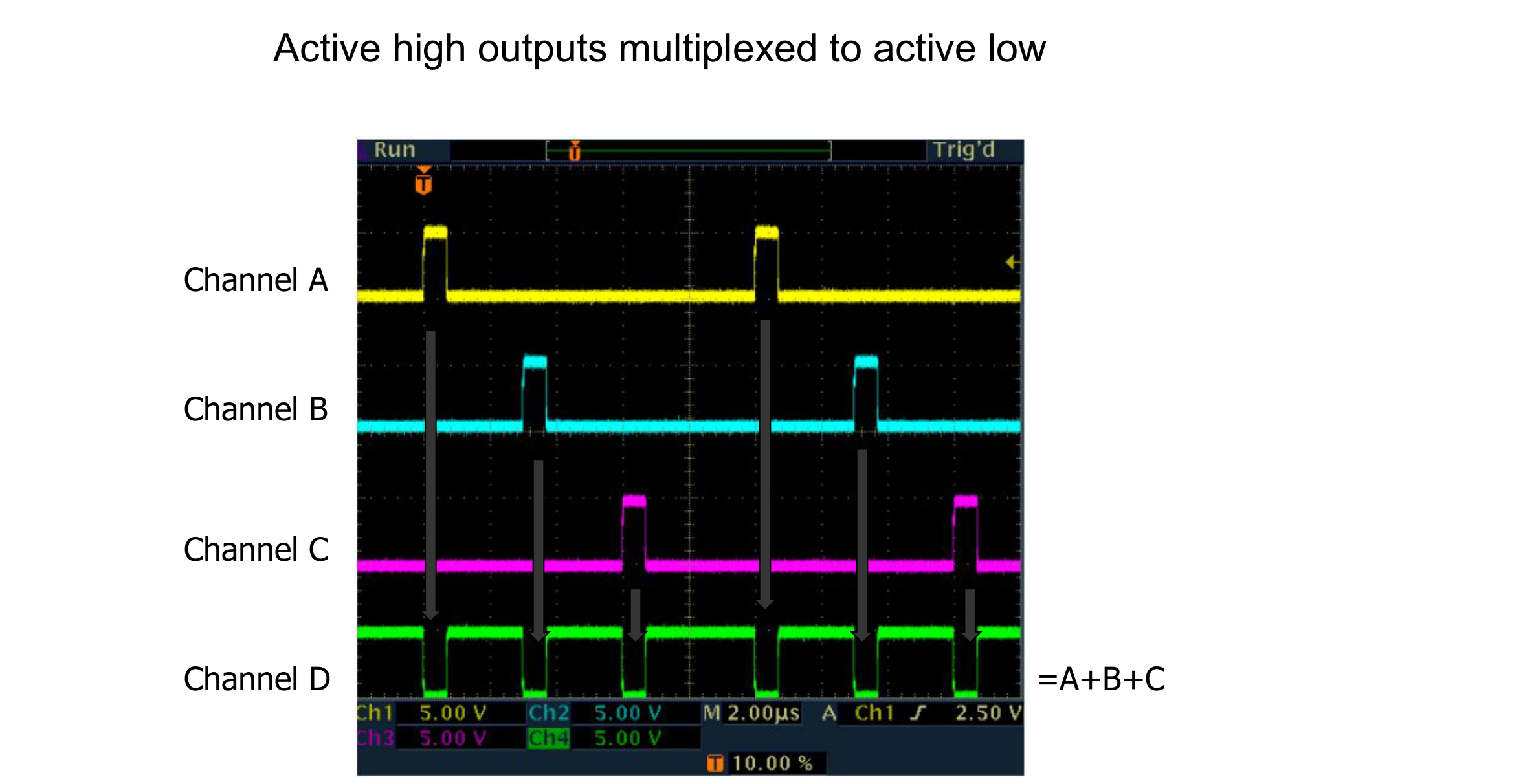
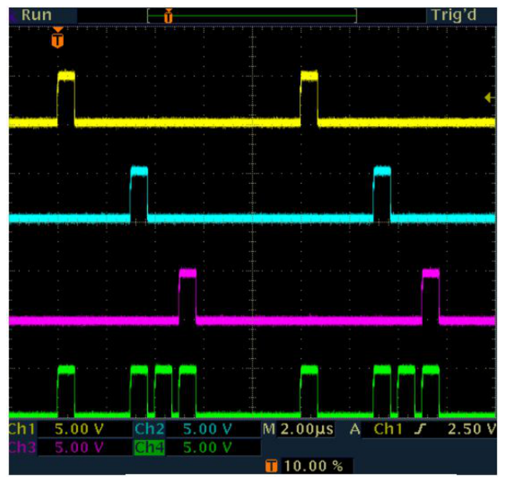
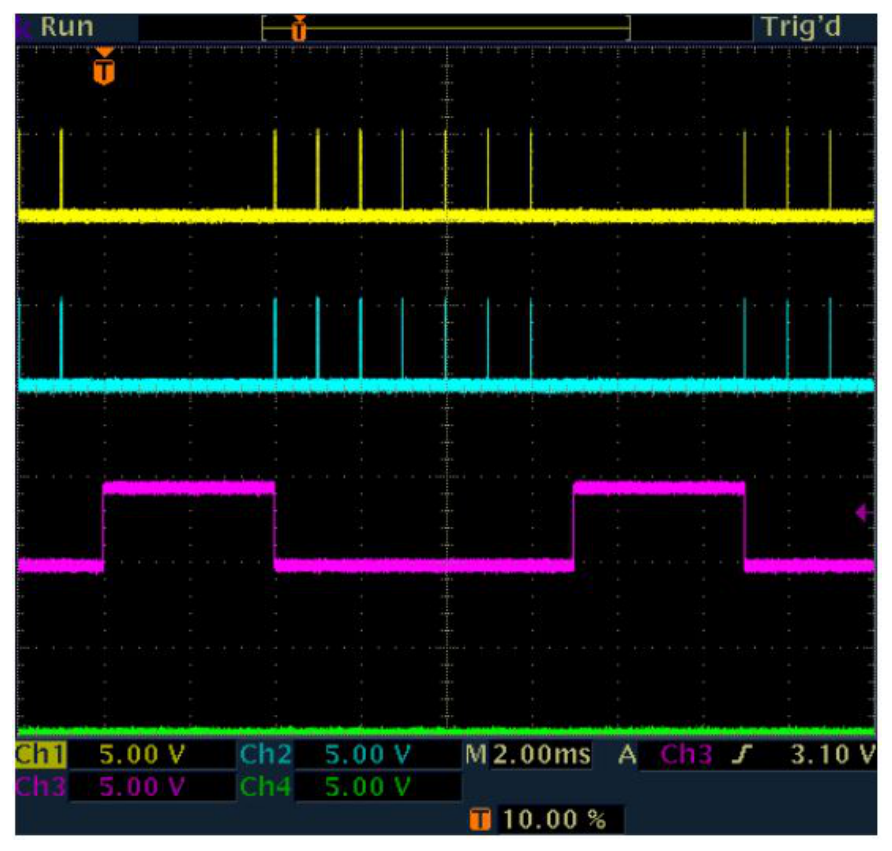
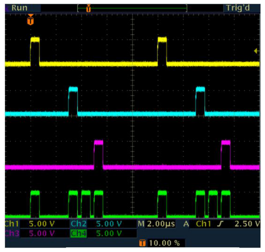
Channel Multiplexing
- Channel multiplexing allows for the combination of any or all channel settings to be output on any of the outputs.
- Channel multiplexing only combines timing events of the channels and not the actual output voltages.
Repeated Multiplexing
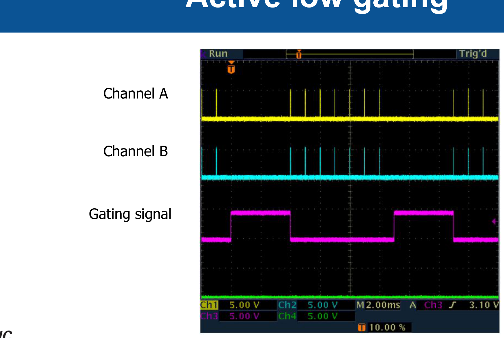
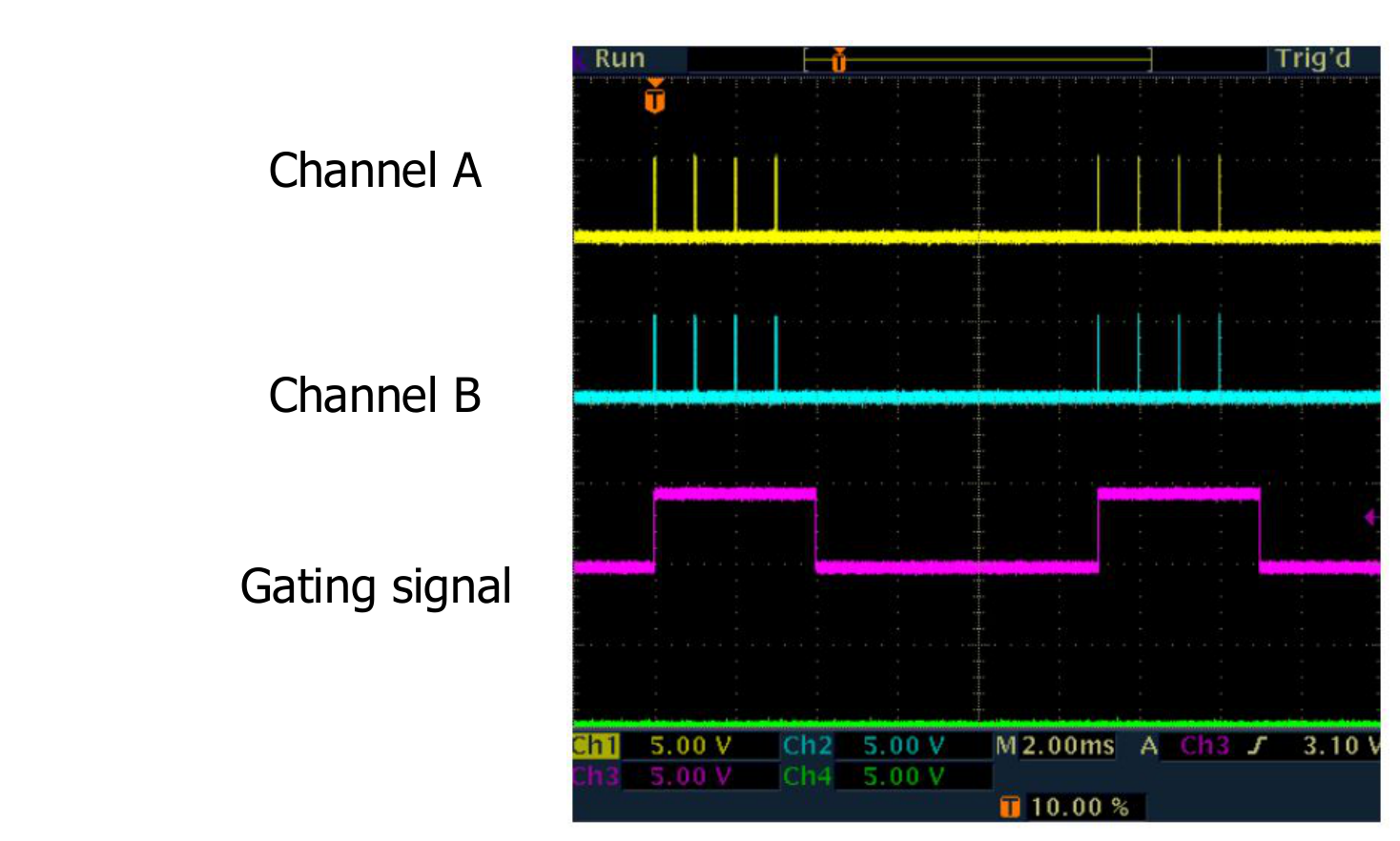
Gating: Output and Pulse Inhibit
- System and Channel Gating can now operate in one of two ways: output inhibit or pulse inhibit.
- Output inhibit: Output is shut off when the gate signal is removed/added regardless of channel timing.
- Pulse inhibit: When the gate signal is removed/added the next pulse does not begin.
Gating: Pulse Inhibit
Active Low Gating
Active High Gating
Pulse and Digital Delay Generator: New Features
New Features
- Gating, Output Inhibit
- Gating, Pulse Inhibit
- Low Jitter Trigger
- Field Programmability
- Selectable Clock-in
- Selectable Clock-out
- Illuminated Run/Stop Button
- Illuminated Channel Enable
- Saved Settings on Power Down
Field Programmability
- Both application and FPGA code is now field upgradable.
- New features can be added to instruments without the need to have the unit sent back.
Illuminated Channel & System Indicators
- Illuminated indicators assist in troubleshooting customer problems over the telephone.
- Channel illumination indicates that the channel is enabled.
- Run/Stop button illumination indicates that the unit is armed.
- Trig/Gate button illumination indicates that the gate or trigger feature is enabled.
Setting Save at Shutdown
- When the unit is shut down, current system and channel settings are saved.
- When the unit is powered back up, the saved settings are automatically restored.
- Saved settings are still available.
Clock-in/Clock-out
- Clock-in/Clock-out is now a standard feature.
- Clock-in can now accept a number of frequencies in addition to 10MHz.
- Clock-out puts out a number of frequencies and the To frequency.
Decreased Jitter
- External trigger jitter has been significantly decreased over the previous pulse generator.
- Jitter is specified as being <800ps RMS.
- Worst case jitter is 2.5ns.
Possible Future Features
- Channel Follower Mode
- Individual Channel Triggers per Outputs
- Input/Output Modules
Compare BNC Models
- Model 575/577
- Ethernet option (removes USB)
- Model 505
- Lower resolution, RS232/GPIB only
Model 575/577
- Clock in/out standard
- All 4 COM types (Ethernet/GPIB add-ons)
- Field upgradeable
- Gating output inhibit/pulse inhibit
Model 575/577 (continued)
- Low amplitude clock in signal
- All 4 COM types (Ethernet/GPIB add-ons)
- 1U high rack mount
- Field upgradeable gating output inhibit/pulse inhibit
Channel Muxing
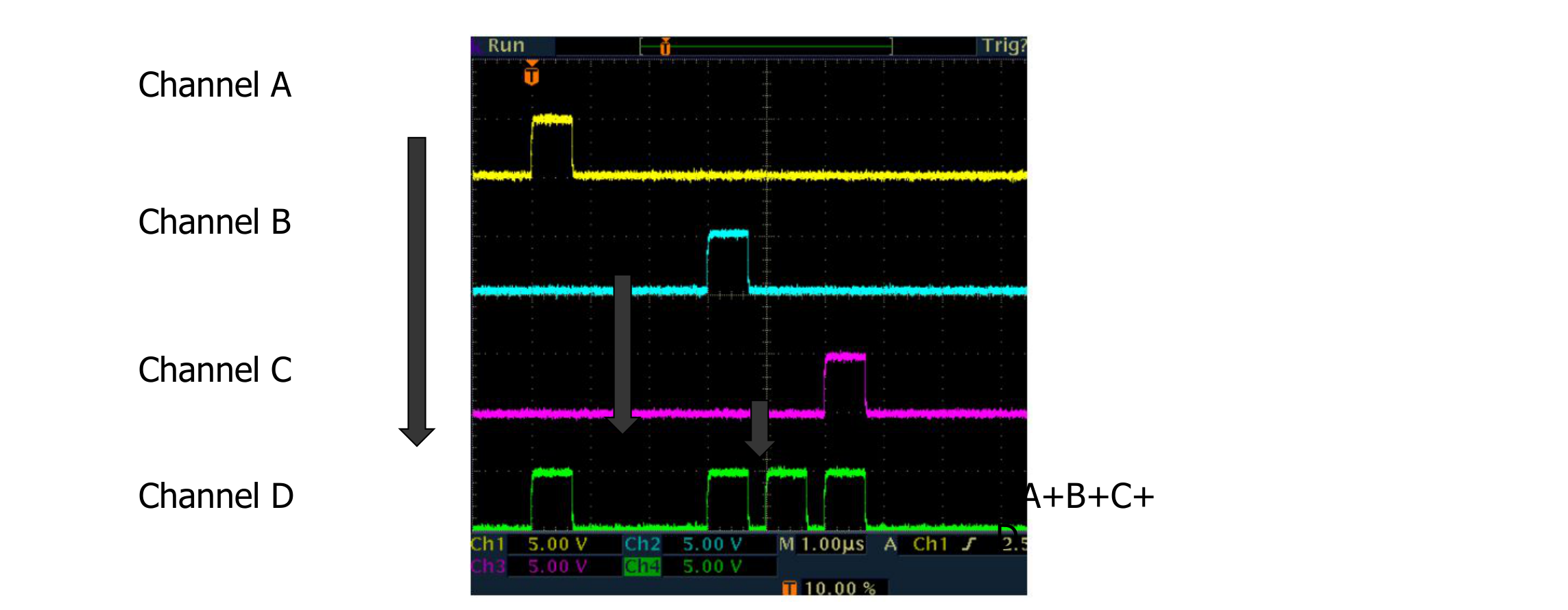
Repeated Muxing
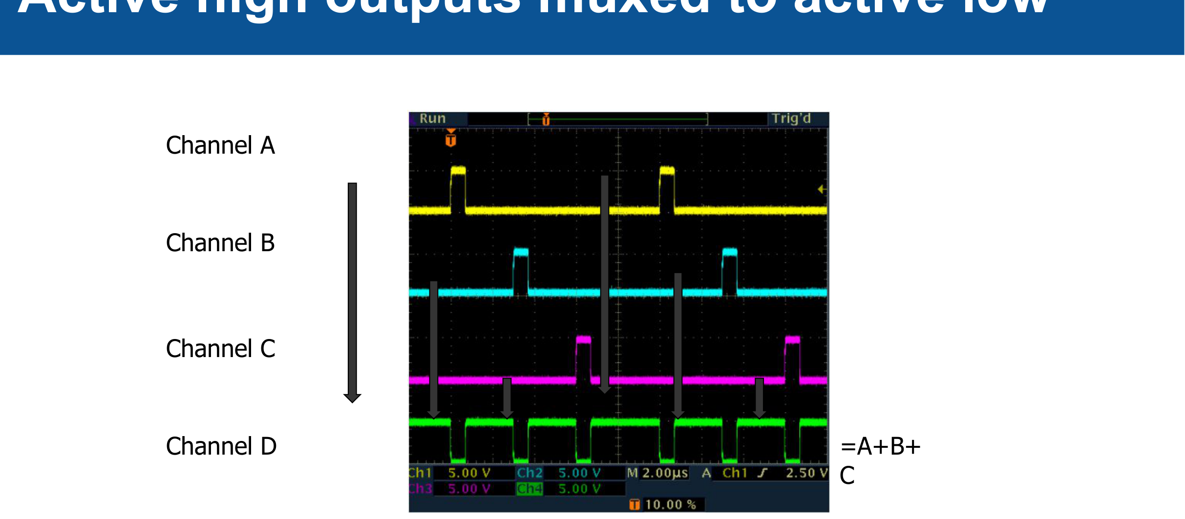
Active High Outputs Muxed to Active Low
Contact BNC Today
Berkeley Nucleonics Corporation
2955 Kerner Blvd, San Rafael, CA 94901
- info@berkeleynucleonics.com
- www.berkeleynucleonics.com
- 800-234-2858